Distributed lighting control system

a technology of lighting control system and distribution system, which is applied in the direction of lighting and heating equipment, lighting support devices, light sources, etc., can solve the problems of difficult control, difficult control, and difficult control, and achieve the effect of reducing the difficulty of adjusting the lighting and controlling the lighting, reducing the difficulty of adjustment, and improving the control

Inactive Publication Date: 2011-07-21
SNAPTRACK
View PDF101 Cites 80 Cited by
  • Summary
  • Abstract
  • Description
  • Claims
  • Application Information

AI Technical Summary

Problems solved by technology

Thus, post-construction modifications or repairs in both residential and commercial settings often require substantial demolition and reconstruction of walls and ceiling.
The resultant expense and inconvenience can render all but the simplest of changes impractical.
Both current methods provide limited ability for control.
One significant limitation in the currently available methods is the requirement of significant time and care during the installation of the lighting system.
Further, because the underlying conduit housing the feed lines (or, in residential settings, the underlying Romex™ pulled through holes drilled in the studs behind the walls) is typically inaccessible and not movable post-construction, great care must be taken in providing sufficient feed lines, switch boxes, and fixtures.
Also, in the second mode of current practice, there is the additional burden of installing the separate electronic switch components themselves.
Reconfiguring the control group requires physically reconfiguring the building infrastructure, which is often not feasible or desirable.
In many cases a type of dimming that works with some fixtures (such as incandescent fixtures) will not function properly with a different fixture (such as a fluorescent fixture).
In the case where separate electronic switch components are placed between each fixture and its power feed, the switch components have no knowledge of the capabilities of the fixture.
In all current practice, installation is difficult, expensive, and time consuming.
In all current practice, reconfiguration is difficult, expensive, and time consuming.
In all current practice, the modes of control are limited and restricted in how they are applied to global sets of fixtures, groups of fixtures, and individual fixtures.

Method used


Image

  • Distributed lighting control system
  • Distributed lighting control system
  • Distributed lighting control system

Examples


Embodiment Construction

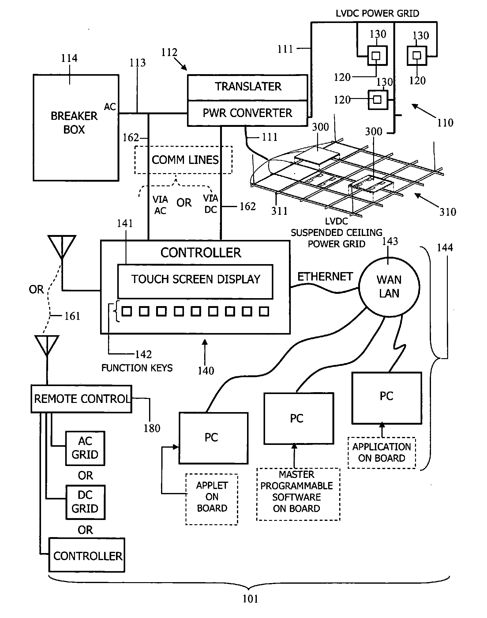
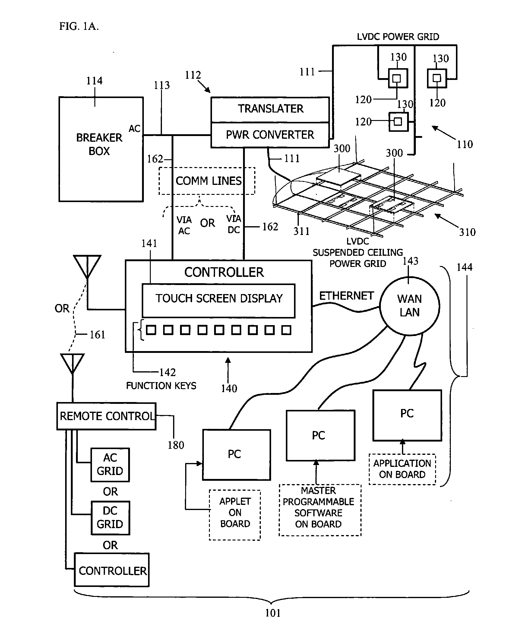
[0026]The present invention is directed to systems and methods for providing distributed lighting control. The Distributed Lighting Control System (DLCS) 101 enables numerous luminaire 120s of different types and with different capabilities to be installed in varied types of installations without regard by installers as to what type of wire has been pulled or (except for the overarching concern of not overloading breakers and circuits) as to the details of what locations the wire has been pulled. The intelligence embedded in the controller and in the luminaire 120s themselves enables an unprecedented level of system control and enables that control to be instantiated post-installation. This dramatic shift in lighting configuration and installation dramatically reduces cost and complexity while increasing performance and flexibility.

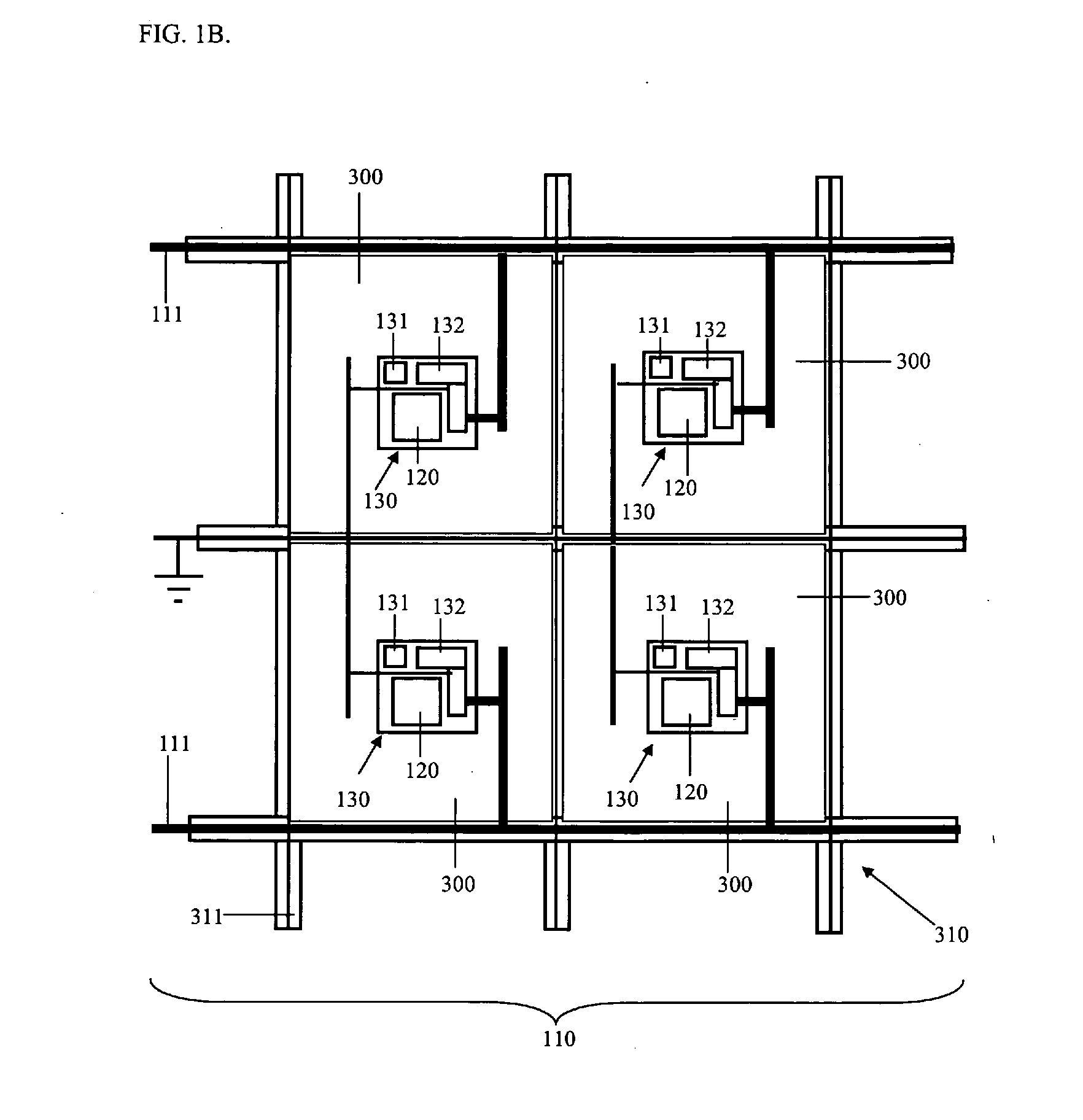
[0027]FIG. 1A illustrates one embodiment of the DLCS 101. In general, the DLCS 101 comprises a power grid 110, at least one luminaire 120 connected to th...


PUM


Abstract

The Distributed Lighting Control System (DLCS) is based upon a distributed lighting system, which imbeds luminaire devices in structural materials such as ceiling tiles and wallboard. Each luminaire device is attached to a power network, and each luminaire device includes, or is directly associated with, an electronic circuit component that controls the activation and operation of the luminaire. In normal operation the power network is energized based on signals conveyed to the circuit through wireless means or through signals imposed upon the power grid. Said signals are generated by the DLCS-controller, which is resident within the structure that contains the DLCS.

Description

[0001]CROSS-REFERENCE TO RELATED PATENT APPLICATIONS[0002]This application is a continuation of International Application No. PCT / US2009 / 005559, filed Oct. 8, 2009, which claims the benefit of Provisional Application U.S. Application 61 / 104,460, filed Oct. 10, 2008. This application is also related to International Application No. PCT / US2009 / 005555, filed Oct. 8, 2009, which claims the benefit of Provisional Application U.S. Application 61 / 104,606, filed Oct. 10, 2008. The disclosures of all of the above-referenced applications are considered part of, and are incorporated by reference in, this disclosure.BACKGROUND OF THE INVENTION[0003]This section is intended to provide a background or context to the invention that is, inter alia, recited in the claims. The description herein may include concepts that could be pursued, but are not necessarily ones that have been previously conceived or pursued. Therefore, unless otherwise indicated herein, what is described in this section is not ...

Claims


Application Information

Patent Timeline
Patent Type & Authority Applications(United States)
IPC IPC(8): H05B37/00H05B37/02
CPCH05B37/0245H05B47/175F21V21/02H05B45/37
Inventor SAMPSELL, JEFFREY B.
Owner SNAPTRACK
Why Eureka
Try Eureka