Removal of stuck blade in a turbine engine

a turbine engine and blade technology, applied in the direction of machines/engines, mechanical equipment, manufacturing tools, etc., can solve the problems of time-consuming, difficult, and high cost of techniques

Active Publication Date: 2011-07-28
SIEMENS ENERGY INC
View PDF11 Cites 11 Cited by
  • Summary
  • Abstract
  • Description
  • Claims
  • Application Information

AI Technical Summary

Benefits of technology

[0020]In accordance with a third aspect of the invention, an apparatus is provided for dislodging stuck blades in a turbine engine. The apparatus comprises a housing, cam structure, and impact structure. The housing is capable of being temporarily secured to a blade disc structure adjacent to a stuck blade to be dislodged. The cam structure is associated with the housing and is adapted to receive an input torque t

Problems solved by technology

Such measures are risky and include, for example, cutting each stuck blade out o

Method used


Image

  • Removal of stuck blade in a turbine engine
  • Removal of stuck blade in a turbine engine
  • Removal of stuck blade in a turbine engine

Examples


Embodiment Construction

[0027]In the following detailed description of the preferred embodiment, reference is made to the accompanying drawings that form a part hereof, and in which is shown by way of illustration, and not by way of limitation, a specific preferred embodiment in which the invention may be practiced. It is to be understood that other embodiments may be utilized and that changes may be made without departing from the spirit and scope of the present invention.

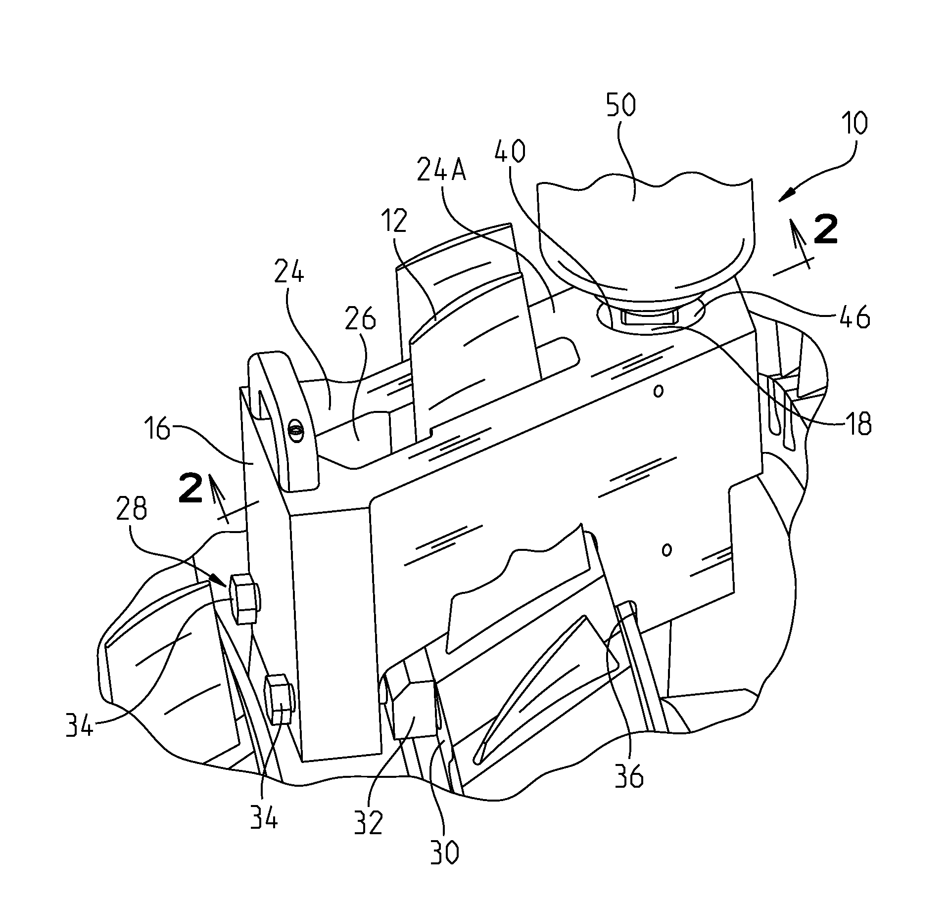
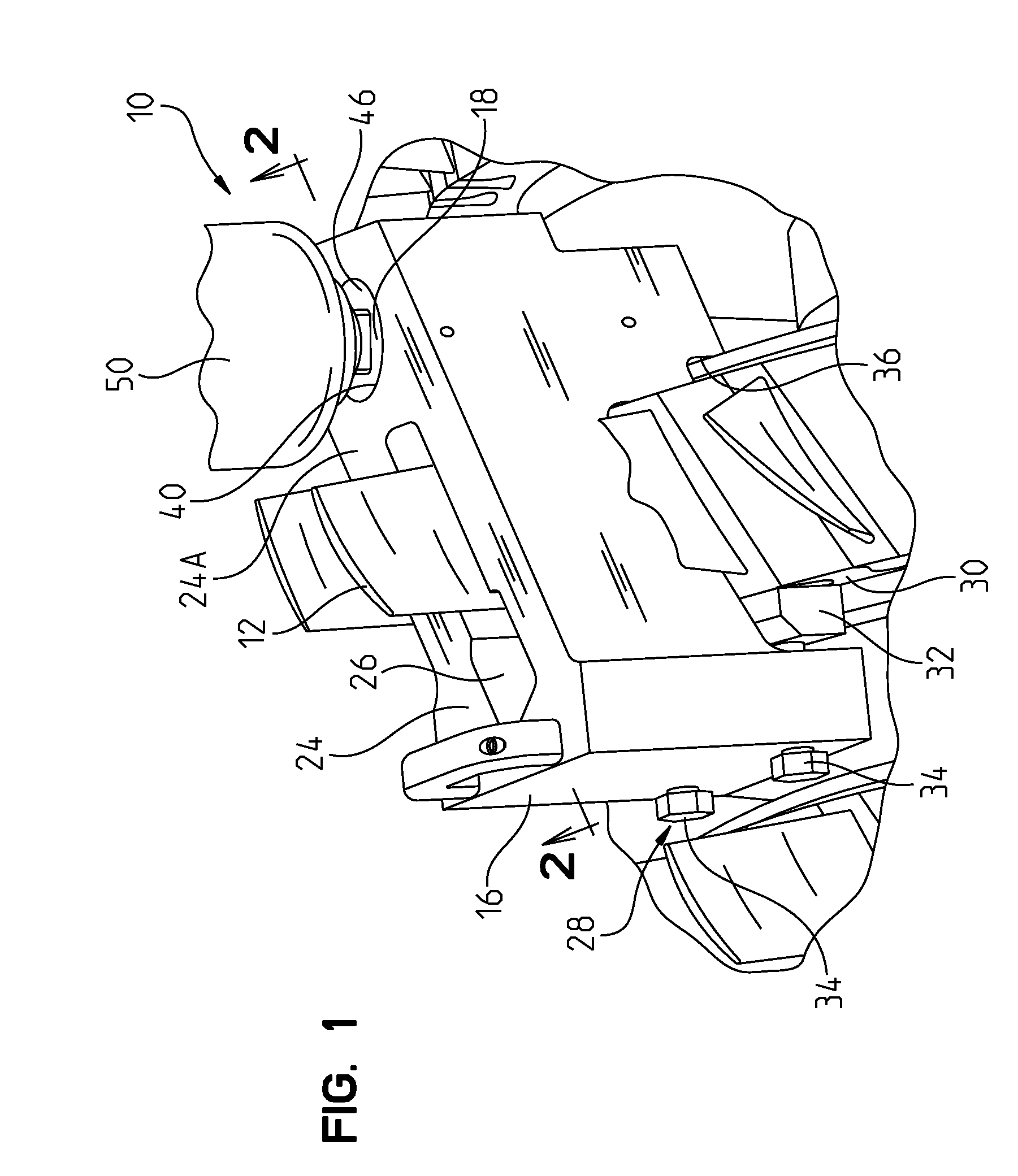
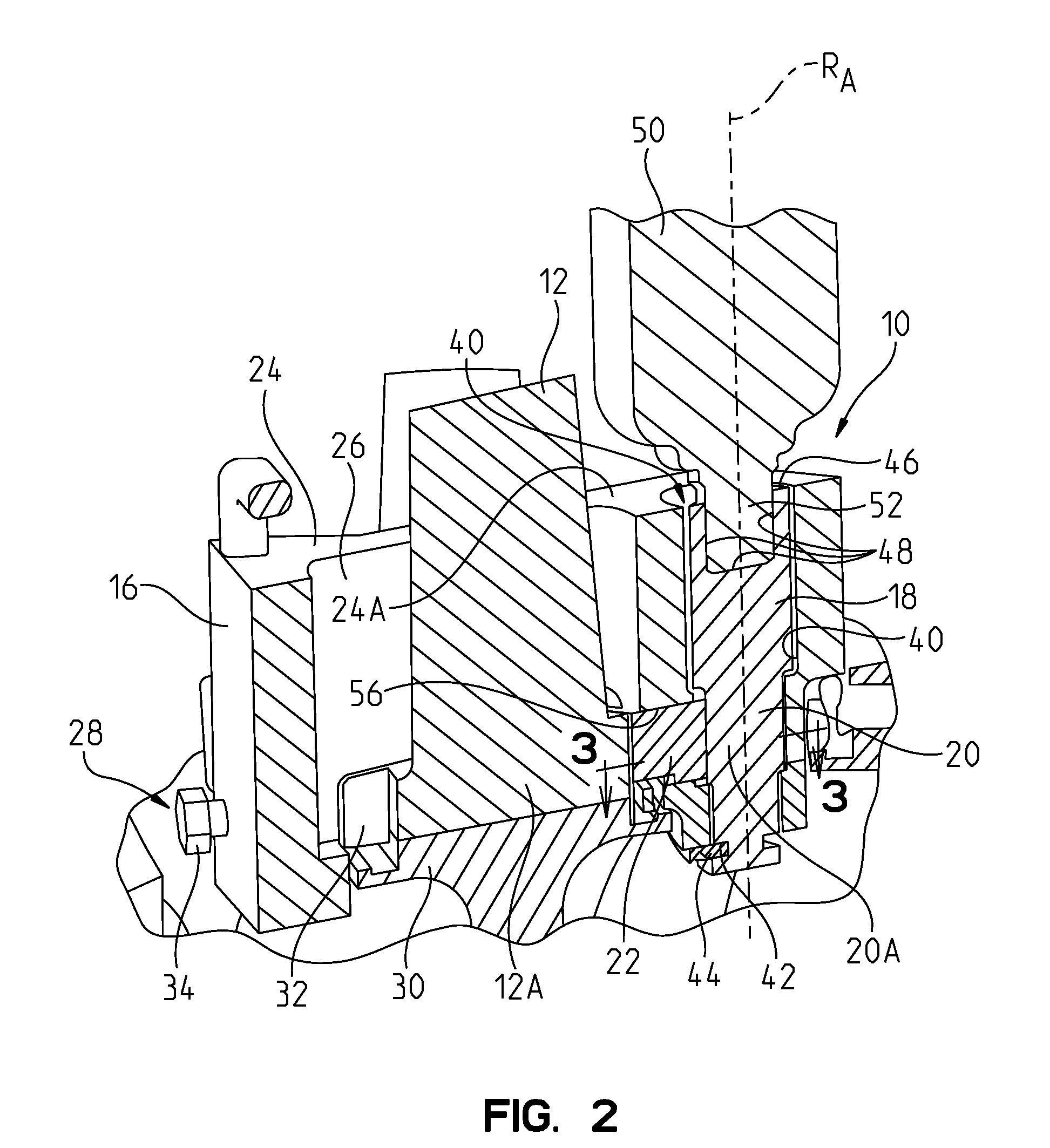
[0028]Referring to FIGS. 1 and 2, an apparatus 10 for dislodging stuck blades 12 in a turbine engine is illustrated. The blades 12 illustrated in FIG. 1 are compressor blades but the apparatus 10 could also be used to dislodge stuck turbine blades. The apparatus 10 comprises a housing 16, torque receiving structure 18, translating structure 20 (FIG. 2), and impact structure 22 (FIG. 2), each of which will be discussed in detail herein. In the embodiment shown, the torque receiving structure 18 and the translating structure 20 are formed ...


PUM

PropertyMeasurementUnit
Forceaaaaaaaaaa
Areaaaaaaaaaaa
Torqueaaaaaaaaaa

Abstract

An apparatus for dislodging stuck blades in a turbine engine. The apparatus includes a housing, cam structure, and impact structure. The housing is capable of being temporarily secured to a blade disc structure adjacent to a stuck blade to be dislodged. The cam structure is associated with the housing and is adapted to receive an input torque that rotates the cam structure, the cam structure capable of translating the input torque into an impact force, the impact force including a component in a desired direction. The impact structure is associated with the housing and is capable of receiving the impact force from the cam structure and exerting the impact force on a root area of the stuck blade for dislodging the stuck blade from the blade disc structure non-destructively.

Description

CROSS REFERENCE TO RELATED APPLICATIONS[0001]This application claims the benefit of U.S. Patent Application Ser. No. 61 / 297,393, filed Jan. 22, 2010, entitled “IMPACT CAM-DRIVEN TOOL TO REMOVE STUCK COMPRESSOR BLADES NON-DESTRUCTIVELY,” the entire disclosure of which is incorporated by reference herein.FIELD OF THE INVENTION[0002]The present invention relates to the non-destructive removal of a stuck blade, such as a compressor blade, in a turbine engine.BACKGROUND OF THE INVENTION[0003]A turbine engine includes a compressor section, a combustion section, and a turbine section. The compressor and turbine sections each include alternating rows of stationary vanes and rotating blades. Blades within the compressor and turbine sections may become stuck to a blade disc structure with which the blades are associated, which blade disc structure structurally supports the blades in the engine. In the event that such stuck blades are in need of being removed from the engine, e.g., for repair ...

Claims


Application Information

Patent Timeline
IPC IPC(8): B23P11/00B23P19/04
CPCB23P19/025B23P19/033F01D5/005F01D25/285Y10T29/53839F05D2230/70Y10T29/53796Y10T29/53843Y10T29/49318F05D2230/80B23P19/02F01D5/00F01D25/28
Inventor SILIETI, MAHMOOD K.LEAGON, JONATHAN M.MOORE, KENNETH L.BARKER, ROBERT D.
Owner SIEMENS ENERGY INC
Why Eureka
Try Eureka