Endotracheal tube protector

a technology for protecting endotracheal tubes and tubes, applied in the field of medical equipment, can solve problems such as damage or pinching of tubes, and achieve the effect of lessening discomfor

Inactive Publication Date: 2011-07-28
SOUTHMEDIC
View PDF17 Cites 12 Cited by
  • Summary
  • Abstract
  • Description
  • Claims
  • Application Information

AI Technical Summary

Benefits of technology

The technical effect of this patent is to create a device called a bite block that helps protect the airway of patients who are being treated with ventilation devices like endotracheal tubes. This device should fit various types of these tubes comfortably without causing any added pain or discomfort for the patient.

Problems solved by technology

The technical problem addressed in this patent is the need for a bite block that can securely protect endotracheal tubes from damage caused by the patient's bite, while accommodating a range of tube sizes and being easily and disengaged engaged with the tube. Existing devices can be insufficiently rigid or can damage the tube if the patient bites too forcefully, and there is a need for a new bite block that can firmly grip and protect the tube while being easily engaged and disengaged.

Method used


Image

  • Endotracheal tube protector
  • Endotracheal tube protector
  • Endotracheal tube protector

Examples


Embodiment Construction

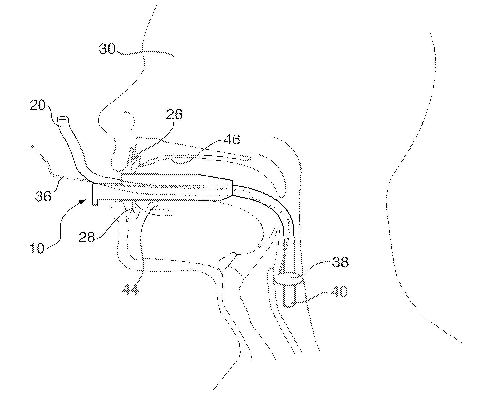
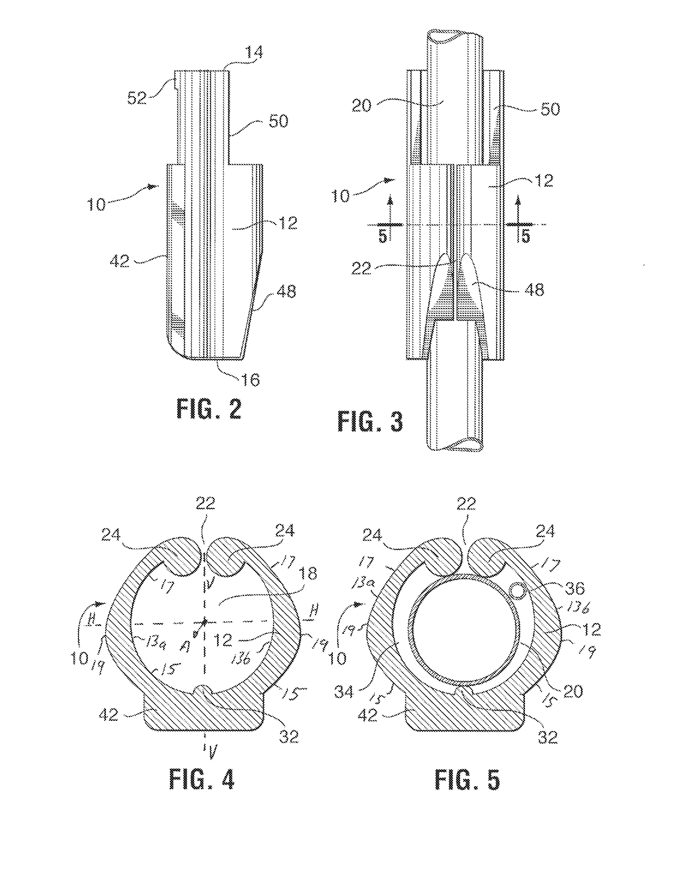
[0034]The endotracheal tube protector 10, also referred to as bite block 10, is configured to retain an endotracheal tube and to provide a robust but comfortable holder for the patient. Bite block 10 is configured to protect an endotracheal tube from inadvertent biting by a patient.

[0035]As seen in FIGS. 1-7, a first embodiment of protector 10 comprises an elongated tubular member 12 formed of resilient material and consisting of an integral, monolithic member. Tubular member 12 has a first end 14 and a second opposed end 16 with an elongate central axis A extending therebetween. The first end 14 extends outwardly from the mouth of a patient when in use, while the second end 16 is located inside the patient's mouth. Tubular member 12 defines a substantially cylindrical cavity 18, extending lengthwise within the device. A conventional endotracheal tube 20 can be retained within cavity 18 with sufficient gripping force to effectively prevent slippage of the tube 20 during normal use. ...


PUM


Abstract

An endotracheal tube protector for use with an endotracheal tube comprises an elongated tubular member having a first end configured to extend out of a patient's mouth when in use and a second end configured to enter the throat of the patient. The tubular member has openings in the first and second ends and defines a substantially cylindrical cavity to hold an endotracheal tube. The tubular member has a longitudinal slit to allow the walls to separate for radial expansion of the cavity. The wall thickness is non-constant, with a thin-walled region which flexes to permit the walls to separate, and a thick-walled region which resists crushing forces acting on the protector. A pair of opposed bosses may extend longitudinally adjacent to the slit, to transmit a clamping force onto the endotracheal tube when contacted by the patient's jaw.

Description


Claims


Application Information

Patent Timeline
Owner SOUTHMEDIC
Why Eureka
Try Eureka