Power reserve display mechanism
a technology of power reserve display and display mechanism, which is applied in the field ofhorology, can solve the problems of widespread complication of power reserve display of watches
- Summary
- Abstract
- Description
- Claims
- Application Information
AI Technical Summary
Benefits of technology
Problems solved by technology
Method used
Image

Examples
Embodiment Construction
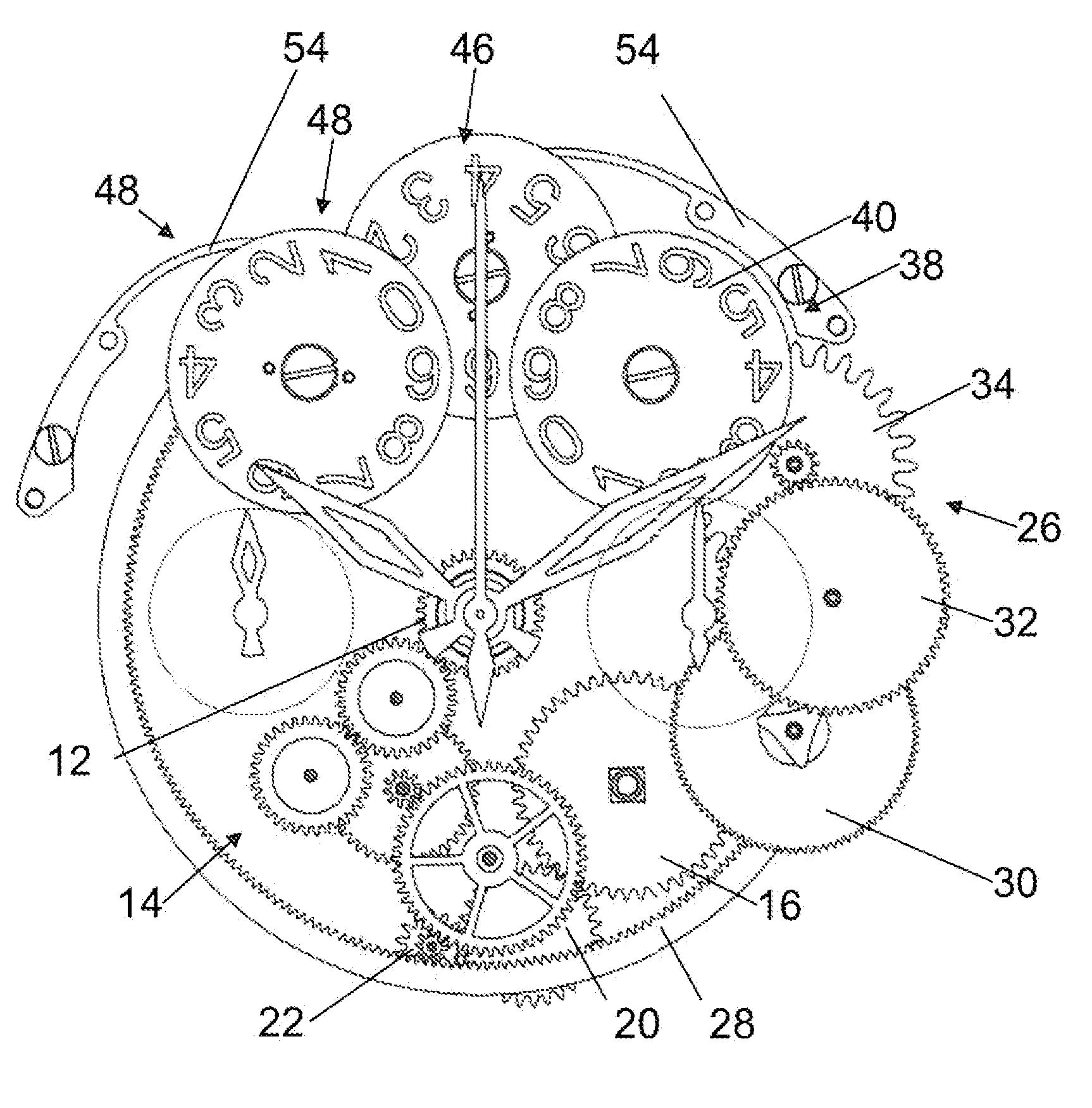
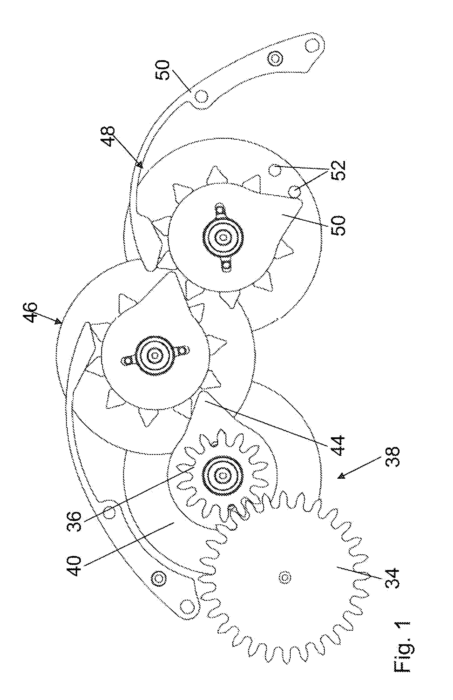
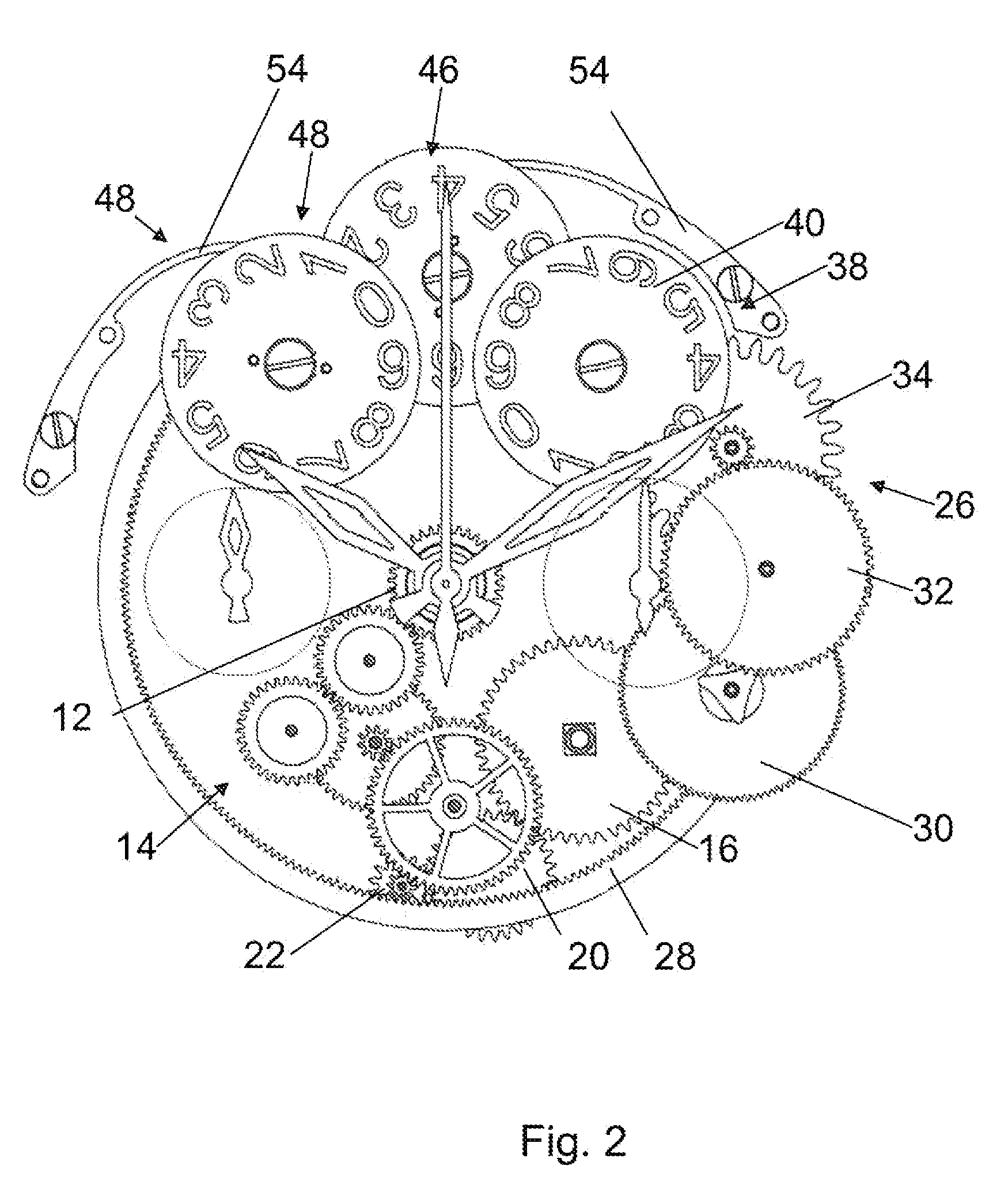
[0015]The mechanism illustrated in FIG. 1 includes an automatic winding system, the force of which is taken from the motion of an oscillating mass 10, not shown, but visible in FIG. 4, pivoting freely under the effect of gravity and the wearer's movements. In the proposed example, the mass 10 is pivoted at the center of the movement and drives a pinion 12. Conventionally, this pinion 12 meshes with a gear train 14, including a reverser system, in order always to drive a ratchet 16 of a barrel 24 in the same direction. Because those skilled in the art know automatic winding systems perfectly, it is not necessary to describe it in detail. Any type of bidirectional system can be used in the context of the invention.
[0016]According to the proposed example, the last wheel of the gear train 14, which we will call ratchet winding wheel 20, is engaged with a first input 22a of a differential 22. This differential 22 can be of the conical type, as generally used in power reserve mechanisms. ...
PUM
 Abstract
Description
Claims
Application Information