
Electronic apparatus and method of controlling electronic apparatus

a technology of electronic equipment and electronic components, applied in the direction of temperature measurement in household appliances, fire alarms, instruments, etc., can solve the problems of user discomfort or low temperature burn, temperature of the casing, and discomfort experienced by users

Active Publication Date: 2011-08-25
SONY CORP
View PDF29 Cites 15 Cited by
  • Summary
  • Abstract
  • Description
  • Claims
  • Application Information

AI Technical Summary

Benefits of technology

[0021]As described above, according to the embodiments of the present invention, it is possible to provide a new or improved electronic apparatus and a method of controlling an electronic apparatus capable of calculating an environmental temperature by measuring the temperature at places where the temperature changes resulting from the heat generation of a heat generation source.

Problems solved by technology

However, when the temperature of the casing becomes too high, the user may feel discomfort or receive a low temperature burn.
However, the discomfort experienced by the user results from the temperature of the casing relative to the use environment of the electronic apparatus rather than from the absolute temperature of the casing.
However, providing the electronic apparatus with a means for directly measuring the temperature in the use environment of the electronic apparatus has a problem in that it results in an increase in the cost of the electronic apparatus.

Method used


Image

  • Electronic apparatus and method of controlling electronic apparatus
  • Electronic apparatus and method of controlling electronic apparatus
  • Electronic apparatus and method of controlling electronic apparatus

Examples


Embodiment Construction

[0033]Hereinafter, preferred embodiments of the present invention will be described in detail with reference to the accompanying drawings. In this specification and the drawings, the same reference numerals refer to the constituent elements having substantially the same functional configuration, and redundant description thereof will be omitted.

[0034]The description will be given in the following order.

[0035][1-1. Exterior Appearance Example of Imaging Apparatus]

[0036][1-2. Functional Configuration of Imaging Apparatus]

[0037][1-3. Heat Dissipation Structure of Imaging Apparatus]

[0038][1-4. Calculation Method of Environmental Temperature]

[0039][1-5. Temperature Monitoring Operation of CMOS Image Sensor]

1. Embodiment of Present Invention

1-1. Exterior Appearance Example of Imaging Apparatus

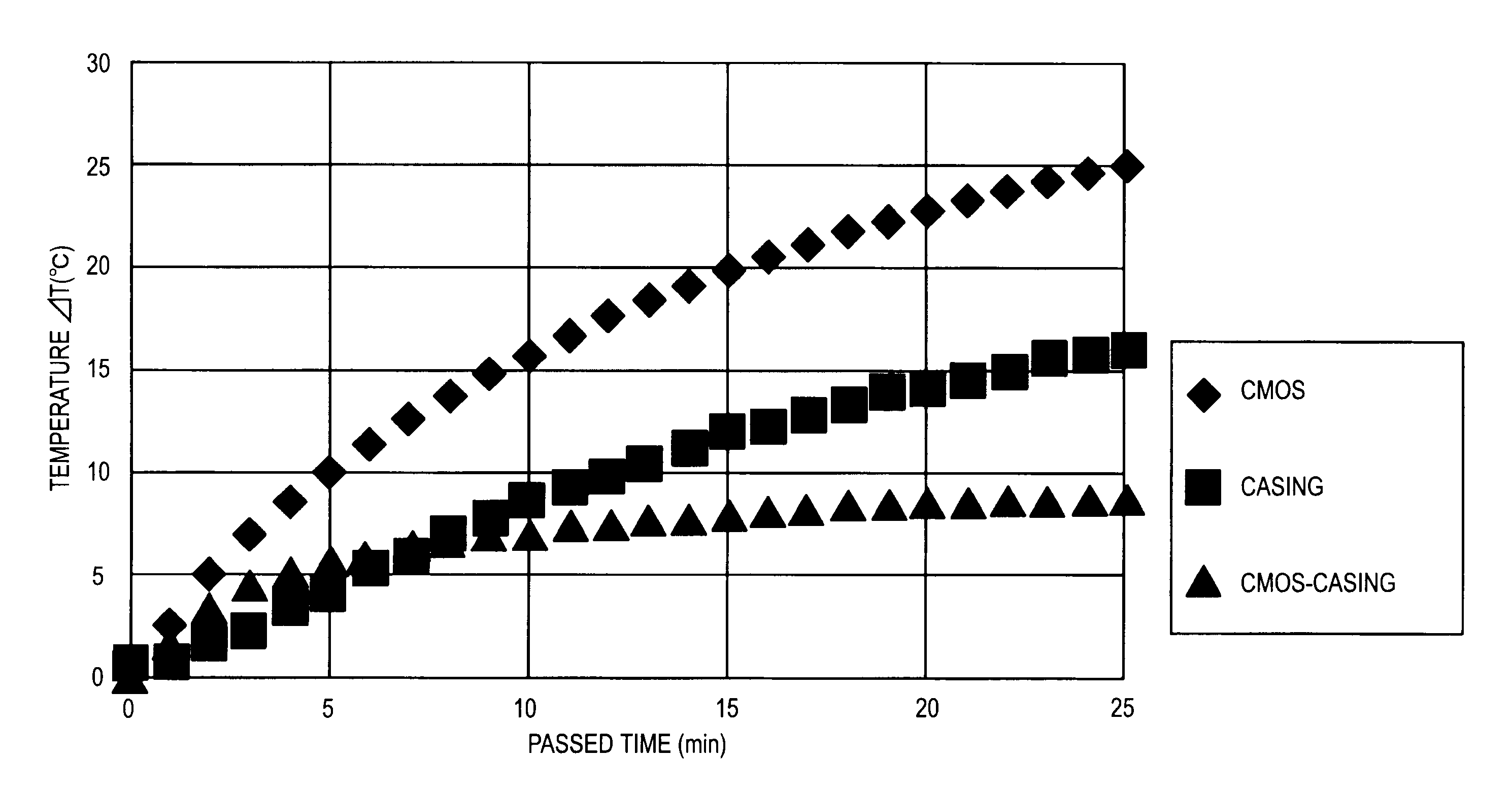
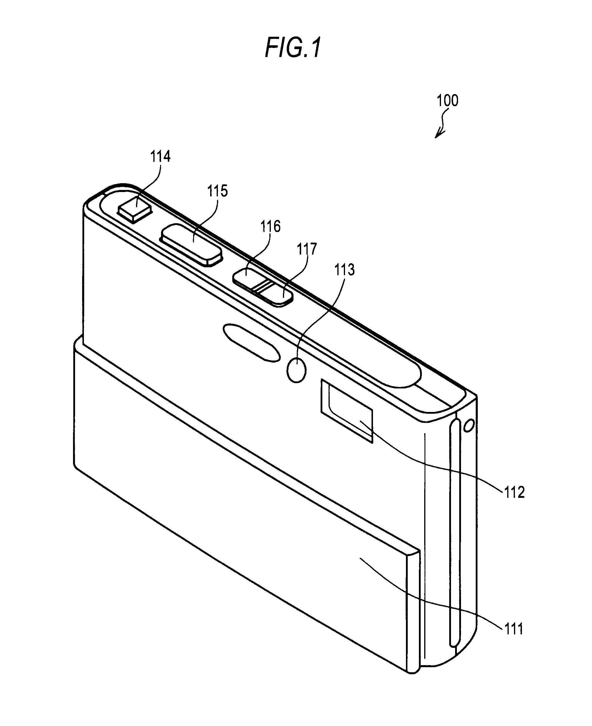
[0040]First, an exterior appearance example of an imaging apparatus which is an example of an electronic apparatus of the present invention will be described with reference to the drawings. FIG. 1 is...


PUM


Abstract

An electronic apparatus includes: a temperature measurement section that measures a temperature of a heat generation source generating heat by consuming power or a temperature of an inner position of a casing of which the temperature changes due to the heat generation of the heat generation source; and an environmental temperature calculation section that calculates a temperature which is calculated using a predetermined relational equation that is different in accordance with a model from a difference between a first temperature measured by the temperature measurement section at a point in time when the heat generation source starts consuming a predetermined amount of power and a second temperature measured by the temperature measurement section at a point in time after the passage of a predetermined period from the start of consumption of a predetermined amount of power by the heat generation source as an environmental temperature in an environment where the casing is placed.

Description

BACKGROUND OF THE INVENTION[0001]1. Field of the Invention[0002]The present invention relates to an electronic apparatus and a method of controlling the electronic apparatus, and more particularly, to a portable electronic apparatus such as a digital camera, a portable phone, or a portable audio player, and a method of controlling such an electronic apparatus.[0003]2. Description of the Related Art[0004]In portable electronic apparatuses such as a digital video camera, a digital still camera, a portable phone, or a portable audio player, it is very important to realize both enhanced performance and size-reduction in order to meet the user's demands. Moreover, with the progress of size-reduction, products in which separate apparatuses are integrated with each other are being commercialized. An example of such products is one in which a digital still camera, a portable audio player, and a portable phone are integrated with each other.[0005]However, enhancement of the performance of el...

Claims


Application Information

Patent Timeline
IPC IPC(8): G08B17/00H02H5/04
CPCG01K7/42G01K7/425G01K2207/00H04N5/23241Y02B60/1275H04N5/2253G06F1/206Y02D10/00H04N23/54H04N23/65H04N23/634
Inventor NAMEKAWA, KIMIYASUKOBAYASHI, HIROYUKI
Owner SONY CORP
Learn More