Canopy tent

a canopy tent and canopy technology, applied in the field of canopies, can solve the problems of uneven installation or disassembly of the tent, height of the tent, and user's excessive operation force, and achieve the effect of rapid and easy installation and disassembly

Active Publication Date: 2011-09-08
SEO JUNG WOO
View PDF12 Cites 5 Cited by
  • Summary
  • Abstract
  • Description
  • Claims
  • Application Information

AI Technical Summary

Benefits of technology

[0014]Accordingly, the present invention has been made to solve the above-mentioned problems occurring in the prior arts, and it is an object of the present invention to provide a canopy tent, which can be rapidly and easily installed and dismantled by an elastic force of a compression spring disposed in a connection device mounted on the top of the tent and by an elastic force of tent poles connected to support poles.
[0015]It is another object of the present invention to provide a canopy tent, which includes a plurality of poles constituting a frame of the tent, first and second joint members for connecting the poles with each other, and a flexure preventing pipe mounted between the first joint member and the second joint member to prevent the installed tent from being collapsed by the external force or stumbled by a draft of air.
[0018]Furthermore, a cover is connected to the top of the sliding member, and the cover has a through hole formed on the upper face thereof to allow a user to connect a cord to the retaining ring formed on one side of the stopper caught to the retaining portion of the sliding member to thereby release the stopper.
[0021]As described above, the canopy tent according to the present invention can be rapidly and easily installed by the elastic force of the compression spring disposed in the connection device and by the elastic force of the poles connected to the support poles and can be rapidly dismantled by the poles, which are folded in a direction of the central axis of the connection device mounted at the top of the tent.
[0022]Furthermore, the canopy tent according to the present invention is prevented from being collapsed by the external force or stumbled by a draft of air because it includes the flexure preventing pipe mounted on the outer face of each pole.

Problems solved by technology

Therefore, as the elevation height of the elevation guide 5 becomes longer, a height of the tent is reduced and the interior space of the tent becomes narrower, and hence, it requires a user's excessive operation force when the tent is installed or dismantled.
Moreover, because the compression spring 4 is exposed to the outside, the user may be injured while installing or dismantling the tent, and the tent may not be installed or dismantled smoothly when the compression spring 4 is corroded.

Method used


Image

  • Canopy tent
  • Canopy tent
  • Canopy tent

Examples


Embodiment Construction

[0034]Reference will be now made in detail to the preferred embodiments of the present invention, which can be easily embodied by those skilled in the art, with reference to the attached drawings.

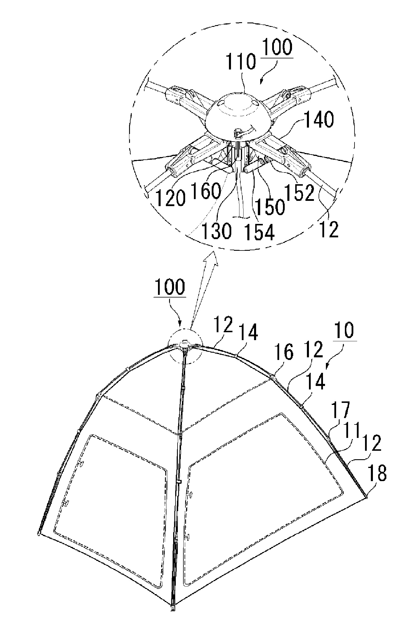
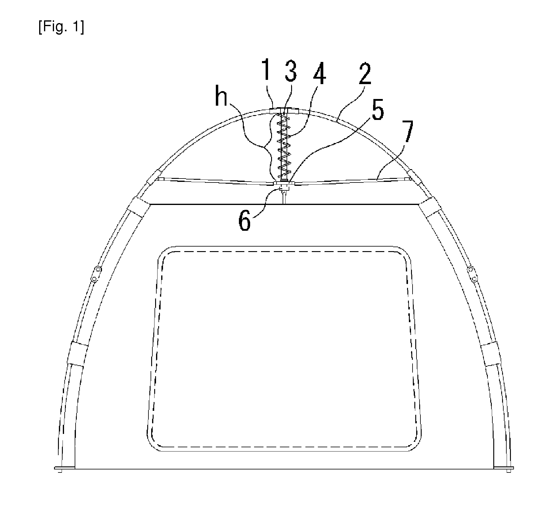
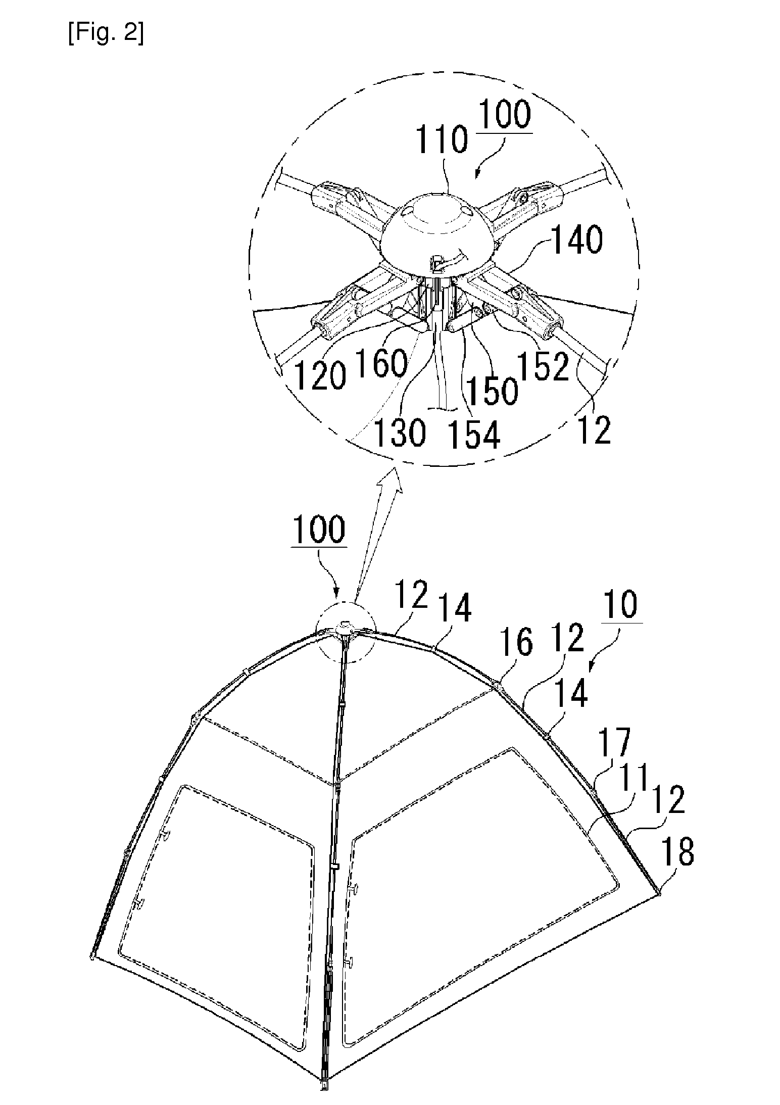
[0035]FIG. 2 is a view showing an example of the use of a canopy tent according to a first preferred embodiment of the present invention, FIG. 3 is a partially exploded view of a connection device according to the first preferred embodiment of the present invention, FIG. 4 is a view showing a folded state of the connection device; and FIG. 5 is a view showing an operation process of a stopper according to the first preferred embodiment of the present invention.

[0036]First, as shown in FIGS. 2 to 5, the canopy tent according to the present invention includes a tent fabric 11, poles 12, sag preventing members 14, connection members 16 and 17, fixing members 18, and a connection device 100.

[0037]The poles 12 constitute a frame of the tent 10 and are mounted in various forms according to the st...


PUM


Abstract

The present invention relates to a canopy tent, comprising: a main body having an outer surface with a plurality of joint rings, and a hollow interior; a sliding member having an outer surface with a plurality of joint rings, and an interior with a downwardly protruding cylinder; a support pole, one end of which is hinged to the joint rings of the main body, and the other end of which is connected to a tent pole for standing the tent fabric upright, and which has a pole connection portion with a joint ring formed at the outer surface thereof; and a joint bar, one end of which is hinged to the joint ring of the sliding member, and the other end of which has one side hinged to a first connection bar hinged to the joint ring of the support pole and the other side hinged to a second connection bar hinged to the joint ring of the main body. The hollow interior of the main body is equipped with a compression spring and a spring holder. The spring holder is coupled to the lower portion of the cylinder. The cylinder of the sliding member is fitted into the hollow interior of the main body from the top of the hollow interior such that the cylinder is movable in the upward and downward directions. The canopy tent of the present invention can be set up or taken down in a rapid and convenient manner using the elastic force of the compression spring arranged in the connection device installed on top of the tent and the elastic force of tent poles connected to the support poles hinged to the connection device.

Description

BACKGROUND OF THE INVENTION[0001]1. Field of the Invention[0002]The present invention relates to a canopy tent, and more particularly, to a canopy tent, which is easy to be installed and dismantled by an elastic force of a compression spring arranged in a connection device mounted on the top of the tent and by an elastic force of tent poles connected to support poles.[0003]2. Background Art[0004]In general, canopy tents are called “collapsible tents” or “folding tents”, and means tents, which can be installed and dismantled while support poles and tent poles constituting a tent frame are expanded or collapsed.[0005]Recently, automatic umbrella style canopy tents configured to be rapidly and easily pitched or closed in a manner similar to the motion of a conventional automatic umbrella have been developed.[0006]As shown in FIG. 1, one of the conventional automatic umbrella style canopy tents includes: a connection member 1 mounted on the top of the tent; a plurality of support poles ...

Claims


Application Information

Patent Timeline
Patent Type & Authority Applications(United States)
IPC IPC(8): E04H15/48
CPCE04H15/42Y10T403/32098Y10T403/342E04H15/48
Inventor SEO, JUNG WOO
Owner SEO JUNG WOO
Why Eureka
Try Eureka