Integrated liquid cooling system for electronic components

a liquid cooling system and electronic component technology, applied in the field of liquid cooling systems, can solve the problems of large space required for discrete components, troublesome and time-consuming installation and removal of cooling systems, and inability to provide satisfactory cooling performance. the effect of rapid and easy installation

Inactive Publication Date: 2007-01-02
HON HAI PRECISION IND CO LTD +1
View PDF16 Cites 23 Cited by
  • Summary
  • Abstract
  • Description
  • Claims
  • Application Information

AI Technical Summary

Benefits of technology

[0007]Accordingly, an object of the present invention is to provide a integrated liquid cooling system which can be rapidly and easily installed to or removed from an electronic enclosure.

Problems solved by technology

The traditional cooling means such as any combinations of heat sinks and cooling fans are increasingly unable to provide satisfactory cooling performance.
Installation and removal of the cooling system can be troublesome and time-consuming.
In addition, a large space for these discrete components is required.

Method used


Image

  • Integrated liquid cooling system for electronic components
  • Integrated liquid cooling system for electronic components
  • Integrated liquid cooling system for electronic components

Examples


Embodiment Construction

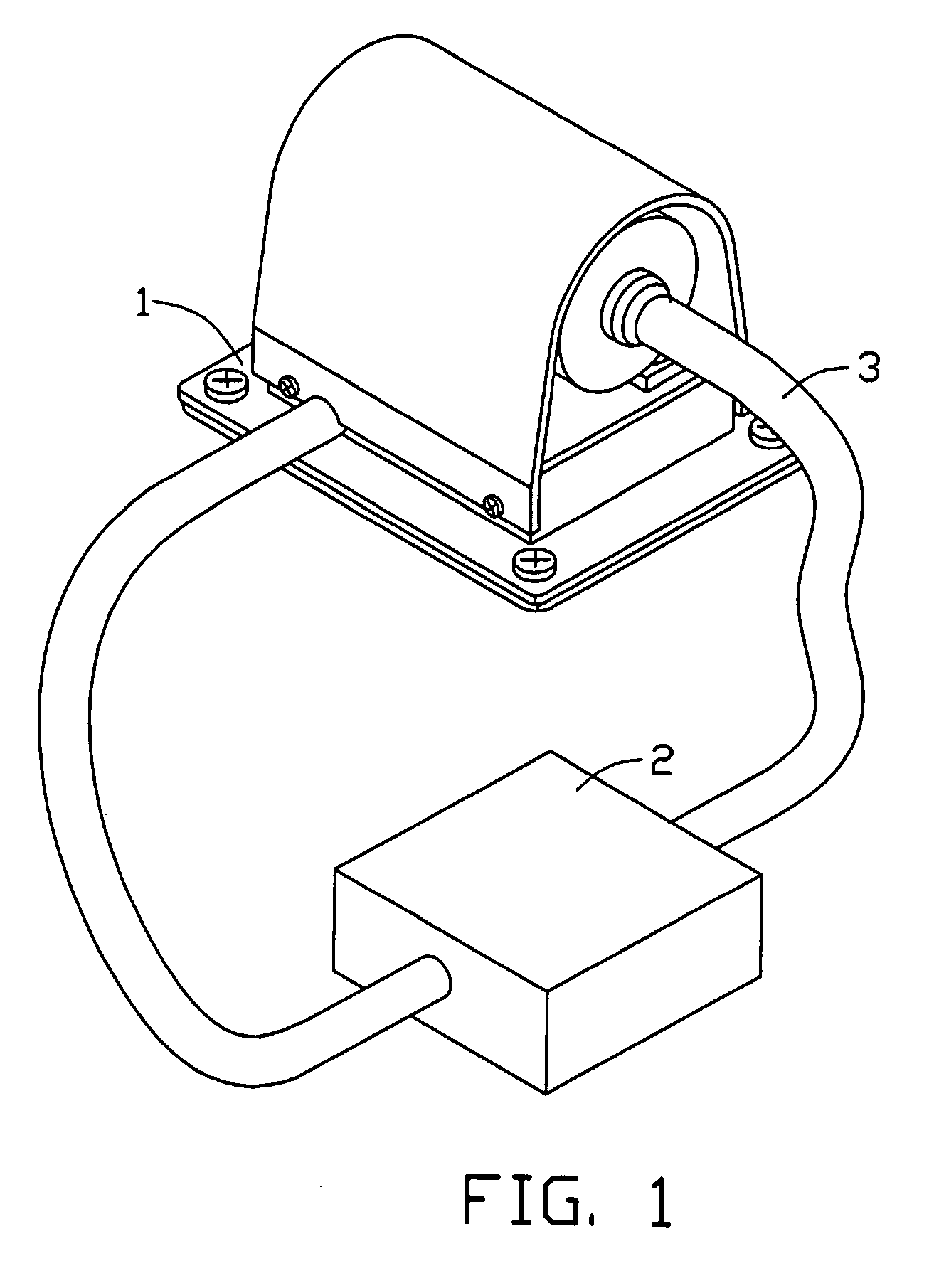
[0015]Referring to FIG. 1, a liquid cooling system in accordance with a preferred embodiment of the present invention comprises a heat absorbing unit 1 for thermally contacting a heat generating component (not shown), and a heat dissipation unit 2. Coolant is filled in the heat absorbing unit 1 for absorbing heat from the heat generating component, and flows through a pipe 3 to the heat dissipation unit 2 for cooling. The cooled coolant then returns to the heat absorbing unit 1 by means of the pipe 3 for a next circulation. The heat dissipation unit 2 is any combination of a heat sink and a cooling fan.

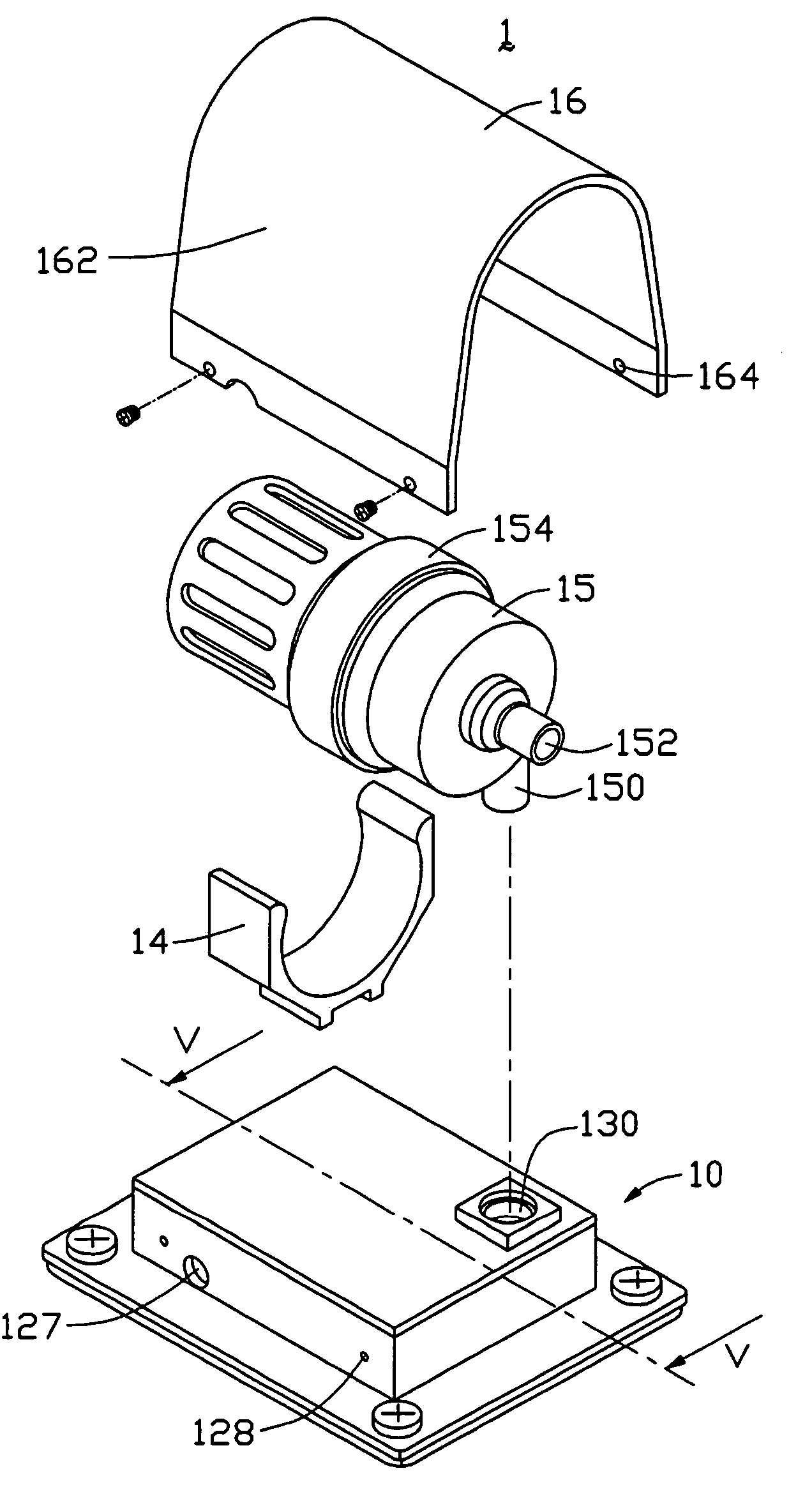
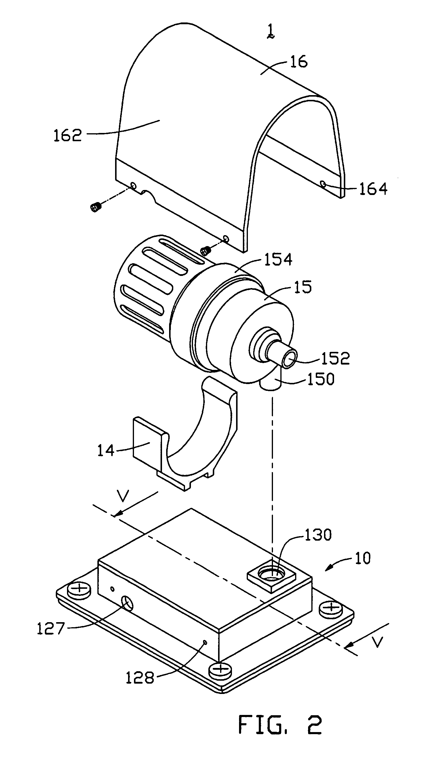
[0016]Referring to FIG. 2, the heat absorbing unit 1 comprises a container 10, and a flow driver such as a pump 15 mounted on the container 10.

[0017]Further referring to FIG. 3, the container 10 comprises a main body 12, a bottom plate 11 hermetically attached to an underside of the body 12, and a top cover 13 hermetically attached to an top side of the body 12. The bottom plate 11 is...


PUM


Abstract

A liquid cooling system includes a container (10) defining communicable first and second chambers (125a, 125b) therein, a pump (15) mounted on the container and having an entrance port (152) in flow communication with the second chamber, and an exit port (150) in flow communication with the first chamber so that the pump, the first chamber, and the second chamber together form a loop for circulation of coolant, and a heat dissipation unit (2) located at the loop for cooling the coolant.

Description

BACKGROUND OF THE INVENTION[0001]1. Field of the Invention[0002]The present invention relates generally to cooling systems, and more particularly to a liquid cooling system for rapidly cooling an electronic component such as a Central Processing Unit (CPU).[0003]2. Related Art[0004]With the continuing development of computer electronics technology, new electronic packages such as the latest CPUs can perform more and more functions. Heat generated by these modern electronic packages has increased commensurately. The heat must be removed from the CPUs to prevent them from becoming unstable or being damaged. The traditional cooling means such as any combinations of heat sinks and cooling fans are increasingly unable to provide satisfactory cooling performance. To obtain an enhanced cooling performance, cooling systems that using liquid cooling technology have been developed for cooling the CPUs.[0005]Chinese patent numbers 98248834.3 and 99210734.2 respectively disclose one kind of the...

Claims


Application Information

Patent Timeline
Patent Type & Authority Patents(United States)
IPC IPC(8): F28D15/00H05K7/20H01L23/473
CPCG06F1/20H01L23/473G06F2200/201H01L2924/0002H01L2924/00
Inventor LEE, HSIEH KUNLAI, CHENG-TIENZHOU, SHI-WEN
Owner HON HAI PRECISION IND CO LTD
Why Eureka
Try Eureka