Cybernetic vibrator device with sensors for in-situ gesture controls

a vibrator and gesture control technology, applied in the field of sex toys, can solve the problems of awkward double-ended dildo sex toy fader-type control, inability to use fader-type control in this form of sex toy, and inability to optimally control the fader-type control of vibrator sex toy,

Active Publication Date: 2011-09-08
STOUT KELSEY MACKENZIE
View PDF5 Cites 63 Cited by
  • Summary
  • Abstract
  • Description
  • Claims
  • Application Information

AI Technical Summary

Benefits of technology

[0007]The touch sensors may be of known types, such as pressure sensors, bend sensors, stretch sensors, compression sensors, temperature sensors, humidity sensors, galvanic skin sensors, photoresistors, accelerometers or other types of sensors. Because they are deployed just at or under the surface of the silicone housing, natural human gestures such as grasp...

Problems solved by technology

Unfortunately, fader-type controls in a vibrator sex toy are not optimal because they are distractions from the very sensations they control.
Such a double-ended dildo may include vibrating motors, but...

Method used


Image

  • Cybernetic vibrator device with sensors for in-situ gesture controls
  • Cybernetic vibrator device with sensors for in-situ gesture controls
  • Cybernetic vibrator device with sensors for in-situ gesture controls

Examples


reversed embodiment

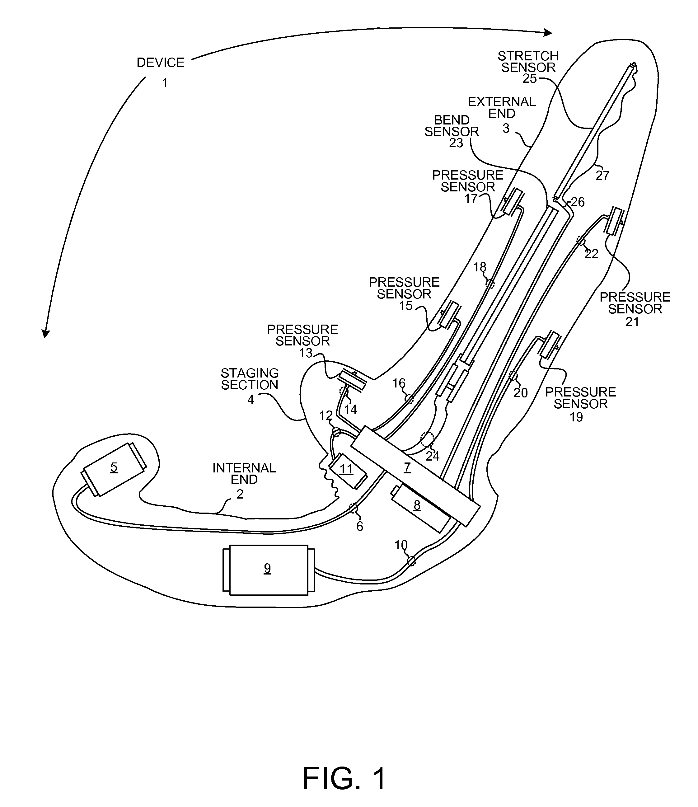
[0034]FIG. 2 is a side view of a second embodiment of a cybernetic vibrator device with reversed ergonomic sensor-based controls, in accordance with another novel aspect. In FIG. 2, touch sensors and their associated motors are disposed in either end of the device 1, such that the user and the user's partner may have simultaneous affects on touch sensors, each effectively controlling a vibrator motor sensed by the other.

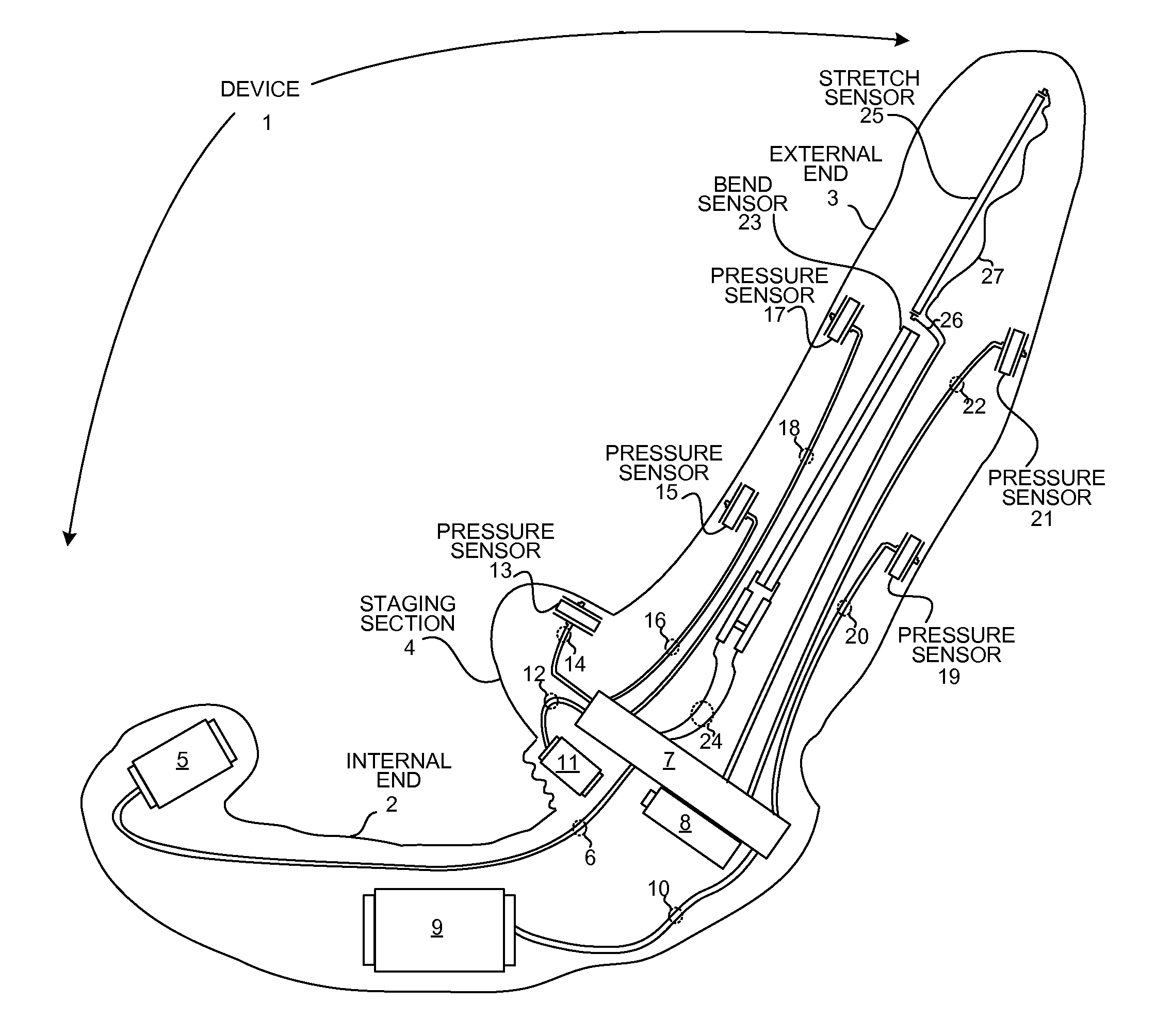
[0035]Device 1 includes an internal end 2, and external end 3 and a (middle) staging section 3. The internal end 2 in the example drawing is shaped to conform to a woman's genitalia, but may have another shape. In the illustrated example, the internal end 2 includes a first force sensor 28 connected by a pair of electrical leads 29 to a control circuit 7 housed in the staging section 4.

[0036]A first example vibrator motor 30 is housed in the external end 3 of the device 1 and connected to the control circuit 7 by a pair of electrical leads 31. The control circuit 7 i...

example circuit

[0040]FIG. 3 is an example circuit diagram showing a force sensor 13 in the control path of a DC vibrator motor 5. Force sensor 13 is a force sensitive resistor (FSR) with, in this example, a resistance at rest of 10,000 ohms. FSR 13 is disposed in a voltage divider arrangement with a second resistor 41 which also has a resistance of 10,000 ohms. Pressure is applied to the FSR 13 when the user of the device or user's partner grasps, pulls or squeezes the device 1 housing surface near where the FSR 13 is situated.

[0041]As increasing pressure from the grasping gesture is translated through the flexible surface of the device 1 to the force sensitive portion of the FSR 13 (indicated by the rounded portion of item 13 in FIG. 3), the resistance of FSR 13 decreases from its maximum of 10,000 ohms. This allows an increased level of VIN to reach the op-amp 42 via the voltage divider formed by FSR 13 and resistor 41. The output of the op-amp 42 can be output to a microprocessor for voltage po...


PUM


Abstract

A vibrator sex toy is provided with touch-based sensors for an ergonomic in-situ method of controlling the operation and intensity of the vibrator. The vibrator sex toy has an internal end, an external end and a middle staging section. The staging section includes a control circuit and batteries. The internal end includes electric vibrator motors connected to the control circuit by wires. The external end includes ergonomically placed touch sensors that behave like variable resistors. The touch sensors respond to natural human gestures such as grasping, stretching, compressing and bending the external end of the sex toy with changes in resistance. The touch sensors are connected to the control circuit by wires and act as potentiometers in the control path of the vibrator motors. The user is able to vary the sensations from the motors intuitively and in-situ by manipulating the external end or applying it to a partner.

Description

CROSS-REFERENCE TO RELATED APPLICATION[0001]This application claims priority under 35 U.S.C. §119(e) from U.S. Provisional Patent Application No. 61 / 310,687, by Stout, “Cybernetic Vibrator With Sensors For Natural Gesture Controls”, filed Mar. 4, 2010, which is incorporated by reference for all purposes.TECHNICAL FIELD[0002]The present invention relates generally to sex toys. More particularly, the present invention relates to a sex toy with in-situ hands-free controls.BACKGROUND INFORMATION[0003]Vibrating sex toys, also known as “vibrators”, are typically equipped with fader-style controls that allow a user to vary the intensity of an electric vibrator motor, thereby altering the sensations produced by the toy. Unfortunately, fader-type controls in a vibrator sex toy are not optimal because they are distractions from the very sensations they control. A more natural and ergonomic method of controlling a vibrator sex toy in-situ is sought.[0004]Additionally, a sex toy is often employ...

Claims


Application Information

Patent Timeline
IPC IPC(8): A61F5/00
CPCA61F5/00A61H2201/0153A61H2201/5028A61H19/44A61H23/00A61H2201/1207A61H2201/169A61H2201/5002A61H2201/5005A61H2201/5007A61H2201/5035A61H2201/5061A61H2201/5064A61H2201/5069A61H2201/5071A61H2201/5079A61H2201/5084A61H2230/655
Inventor STOUT, KELSEY MACKENZIE
Owner STOUT KELSEY MACKENZIE
Why Eureka
Try Eureka