Blood pressure measuring device with improved display

a technology of blood pressure measurement and display device, which is applied in the field of blood pressure measurement device, can solve the problems of enlarge the display device, difficult to determine the relative high and low levels of blood pressure value in a glance, and difficult to understand the tendency of blood pressure in a momen

Inactive Publication Date: 2011-09-08
OMRON HEALTHCARE CO LTD
View PDF9 Cites 9 Cited by
  • Summary
  • Abstract
  • Description
  • Claims
  • Application Information

AI Technical Summary

Benefits of technology

[0009]It is an object of the present invention to provide a blood pressure measurement device having a display mode enabling the level of the blood pressure value, which is difficult to understand in digital display, to be intuitively understood.
[0010]Another object of the present invention is to provide a blood pressure measurement device enabling the transition state of the blood pressure value to be determinable in a glance even in a small display region.
[0020]According to the present invention, the blood pressure indicated by the blood pressure data is displayed with a rectangular bar divided by a plurality of segments of a predetermined unit and simultaneously displayed with a numerical value in the same screen of the display unit. As a result, the user can intuitively understand the level of the blood pressure value that was hard to recognize in the digital display.

Problems solved by technology

Such display method is effective if the measurer recognizes the measurement result as an accurate value, but the relative high and low levels of the blood pressure value is difficult to determine in a glance.
Furthermore, when a plurality of history data is continuously called and displayed to know the transition state of the blood pressure value in time series, the tendency of the blood pressure is difficult to understand instantaneously.
However, the display of the determination of the blood pressure section is not made in the devices of such documents, and hence the measurer (user) himself / herself needs to perform the determination based on the blood pressure measurement result.
However, a display region for displaying the time series data of a constant range is necessary, which enlarges the display device.

Method used


Image

  • Blood pressure measuring device with improved display
  • Blood pressure measuring device with improved display
  • Blood pressure measuring device with improved display

Examples


Embodiment Construction

[0037]Each embodiment of the present invention will be described in detail with reference to the drawings. The same reference numerals are denoted for the same or corresponding portions throughout the drawings, and the description thereof will not be repeated.

[0038](Automatic Winding Electronic Sphygmomanometer)

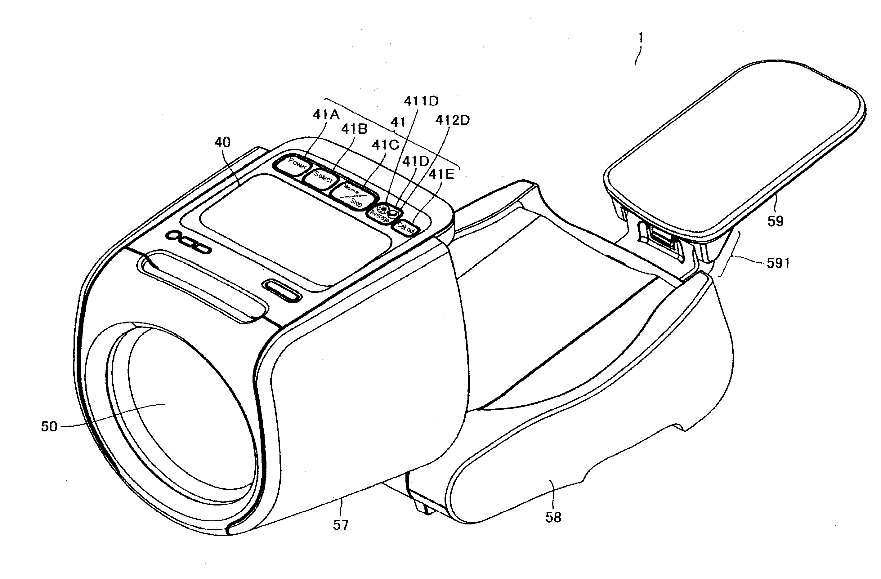
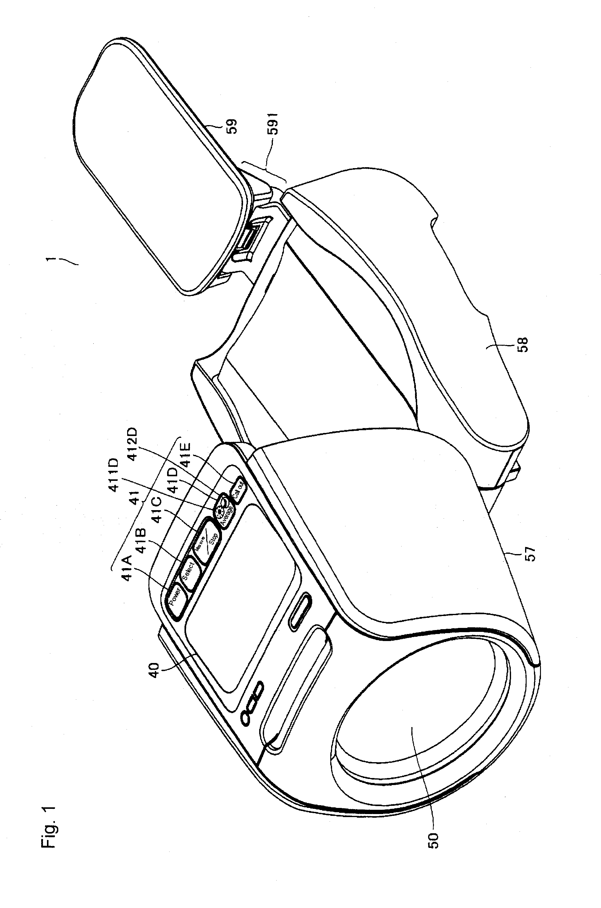
[0039]An automatic winding electronic sphygmomanometer 1 having the configuration of FIG. 1 to FIG. 4 is illustrated as a blood pressure measurement device according to the present invention.

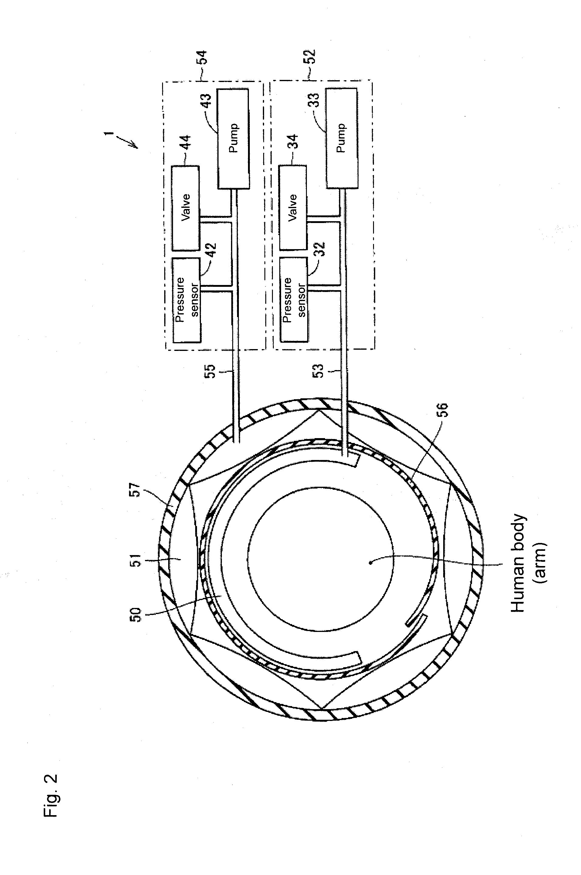
[0040]With reference to FIG. 2 to FIG. 4, the automatic winding electronic sphygmomanometer 1 includes a blood pressure measurement air bladder 50, a compressing and fixing air bladder 51 for compressing the blood pressure measurement air bladder 50 and fixing the same at the measurement site, a blood pressure measurement air system 52 for supplying or discharging air to and from the blood pressure measurement air bladder 50 through a tube 53, and an amplifier 35, a pump drive circuit 36,...


PUM


Abstract

Blood pressure data read from a storage unit is displayed using a blood pressure level bar divided into rectangular segments, and a numerical value of data in a display unit. During the blood pressure measurement, the blood pressure level bar and the numerical value are displayed according to the rise and fall of the detected blood pressure in the display unit. A reference value for determining high blood pressure is displayed in association with the blood pressure level bar. The person to be measured can grasp the blood pressure section to which the measured blood pressure corresponds based on the reference value. The person to be measured can readily grasp the transition of the blood pressure value with the blood pressure level bar even if the size of the display region of the display unit is small.

Description

[0001]This is a continuation of application Serial No. PCT / JP2009 / 068649 filed Oct. 30, 2009, the contents of which are incorporated herein by reference.BACKGROUND OF THE INVENTION[0002]1. Field of the Invention[0003]The present invention relates to blood pressure measurement devices, and in particular, to a blood pressure measurement device for displaying a blood pressure measurement result with a bar graph.[0004]2. Description of the Background Art[0005]The conventional electronic sphygmomanometer digitally displays the blood pressure measurement result such as the systolic blood pressure value and the diastolic blood pressure value to notify the measurer (user). The measurer is able to know the past blood pressure value by calling and displaying the history of the blood pressure measurement result. Such display method is effective if the measurer recognizes the measurement result as an accurate value, but the relative high and low levels of the blood pressure value is difficult t...

Claims


Application Information

Patent Timeline
Patent Type & Authority Applications(United States)
IPC IPC(8): A61B5/022
CPCA61B5/0225A61B5/743A61B2560/0406A61B5/02141
Inventor MARUTA, KOJIKUKITA, TOMOHIROARIDOME, KENJITAKEOKA, KOHEIMITSUNAMI, YUKIKO
Owner OMRON HEALTHCARE CO LTD
Why Eureka
Try Eureka