
Tendon repair implant and method of arthroscopic implantation

a technology of tendons and implants, applied in the field of orthopaedic implants and methods of treatment, can solve the problems of nothing done to repair the tendon, load sharing, etc., and achieve the effect of strengthening the native tendon

Active Publication Date: 2011-09-15
ROTATION MEDICAL
View PDF110 Cites 97 Cited by
  • Summary
  • Abstract
  • Description
  • Claims
  • Application Information

AI Technical Summary

Benefits of technology

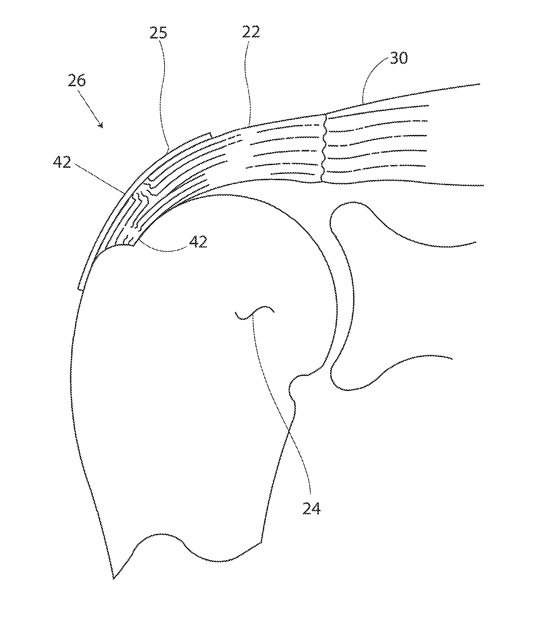
[0014]In some embodiments, the tendon repair implant can include a sheet-like structure having desired properties and format for repairing the partial thickness tear. In particular, the sheet-like structure may be constructed to have a first compact configuration for delivery from an arthroscopic instrument and a second planar configuration defined by a longitudinal, lateral and thickness dimension with a longitudinal surface generally conformable to a bursal side surface of the supraspinatus tendon when positioned thereon. The sheet-like structure may have a tensile modulus of about 5 MPa to about 100 MPa in the range of 1% to 3% strain in the longitudinal dimension and a porosity of about 30% to about 90%. Further the sheet-like structure may include longitudinal pathways defined in the thickness dimension for at least some tissue in-growth oriented in the longitudinal dimension. The oriented tissue in-growth coupled with cyclic straining and load sharing with the implant result in remodeling of new tissue in-growth to form oriented tendon-like tissue that strengthens the native tendon.

Problems solved by technology

Other current procedures may include debridement of degenerated tendon, but again nothing is done to repair the tendon.
In some embodiments, the physical properties of the sheet-like structure result in load sharing between native tendon and the tendon repair implant immediately following surgery.

Method used


Image

  • Tendon repair implant and method of arthroscopic implantation
  • Tendon repair implant and method of arthroscopic implantation
  • Tendon repair implant and method of arthroscopic implantation

Examples


Embodiment Construction

[0030]The following detailed description should be read with reference to the drawings in which similar elements in different drawings are numbered the same. The drawings, which are not necessarily to scale, depict illustrative embodiments and are not intended to limit the scope of the invention.

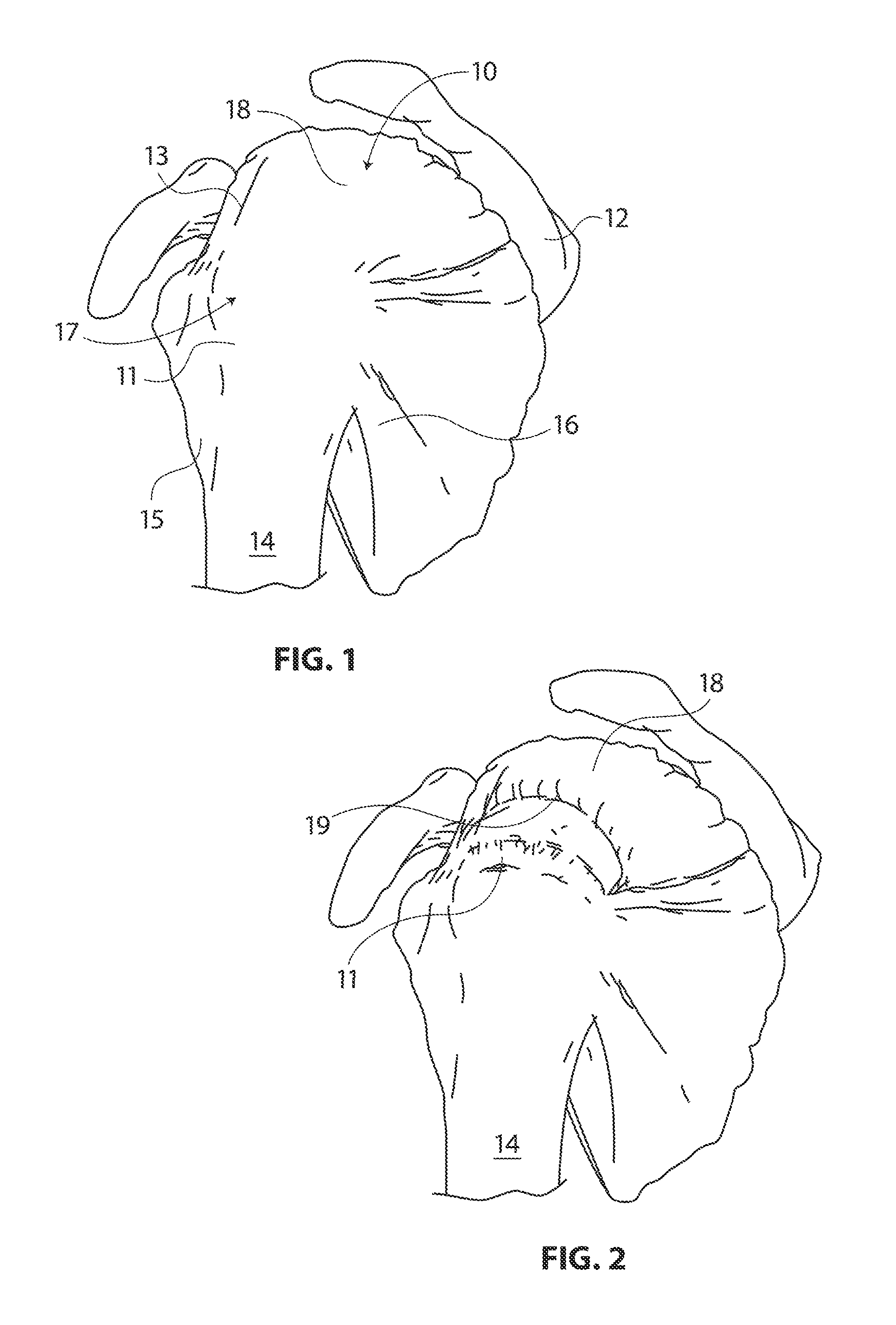
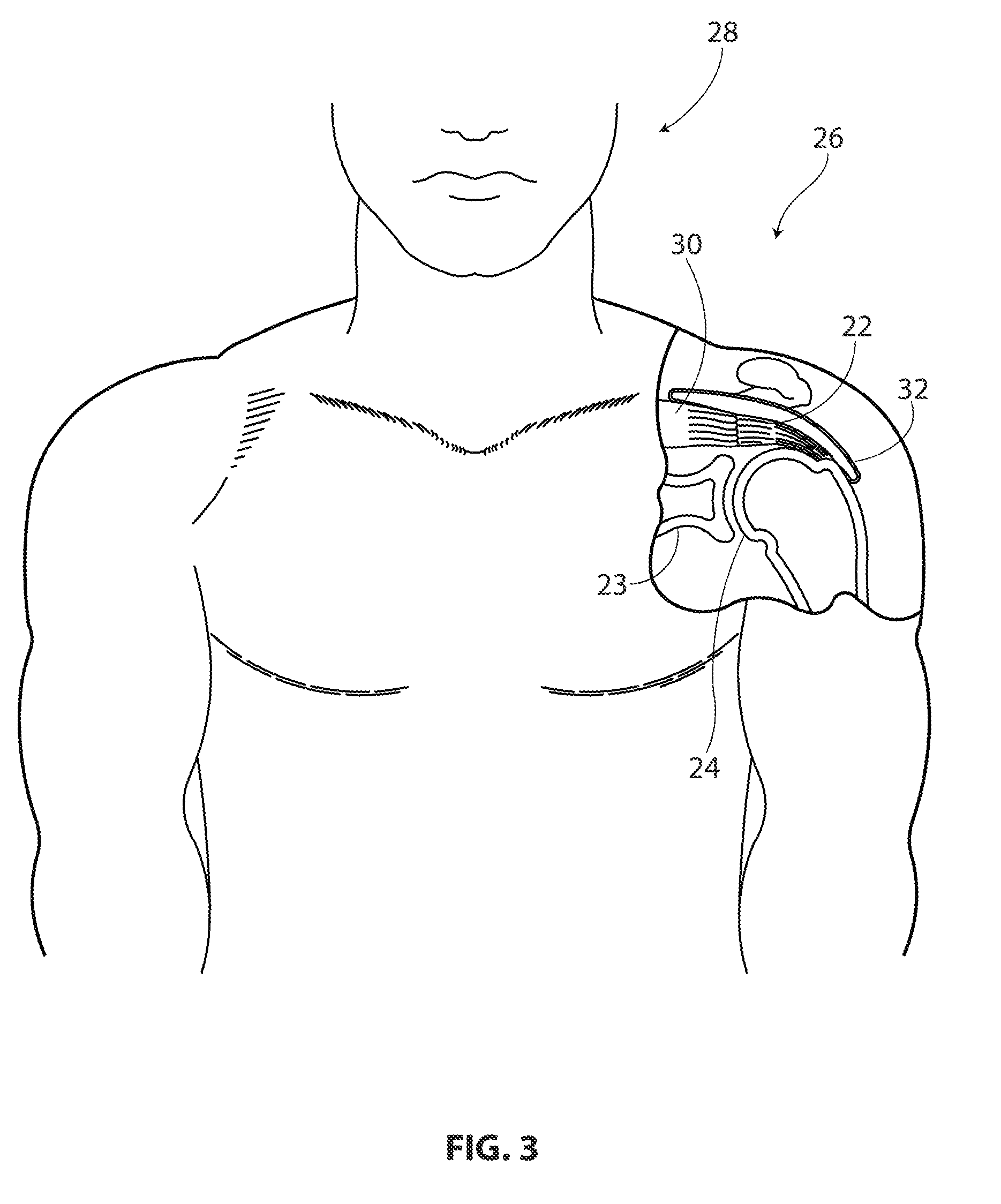
[0031]FIG. 3 is a stylized anterior view of a patient 28. For purposes of illustration, a shoulder 26 of patient 28 is shown in cross-section in FIG. 3. Shoulder 26 includes a humerus 24 and a scapula 23. The movement of humerus 24 relative to scapula 23 is controlled by the muscles of the rotator cuff as previously discussed with respect to FIG. 1. For purposes of illustration, only the supraspinatus 30 is shown in FIG. 3. With reference to FIG. 3, it will be appreciated that a distal tendon 22 of the supraspinatus 30 (hereinafter referred to as the supraspinatus tendon) meets humerus 24 at an insertion point 32.

[0032]FIG. 4 is an enlarged cross sectional view of shoulder 26 shown in the pr...


PUM

PropertyMeasurementUnit
porosityaaaaaaaaaa
porosityaaaaaaaaaa
thicknessaaaaaaaaaa

Abstract

A tendon repair implant for treatment of a partial thickness tear in the supraspinatus tendon of the shoulder is provided. The implant may incorporate features of rapid deployment and fixation by arthroscopic means that compliment current procedures; tensile properties that result in desired sharing of anatomical load between the implant and native tendon during rehabilitation; selected porosity and longitudinal pathways for tissue in-growth; sufficient cyclic straining of the implant in the longitudinal direction to promote remodeling of new tissue to tendon-like tissue; and, may include a bioresorbable construction to provide transfer of additional load to new tendon-like tissue and native tendon over time.

Description

CROSS REFERENCE TO RELATED APPLICATIONS[0001]This application claims benefit to U.S. Provisional Patent Application No. 61 / 313,113, entitled, “TENDON REPAIR IMPLANT AND METHOD OF ARTHROSCOPIC IMPLANTATION” filed on Mar. 11, 2010.INCORPORATION BY REFERENCE[0002]This present application is related to: U.S. patent application Ser. No. 12 / 684,774, filed Jan. 8, 2010; U.S. patent application Ser. No. 12 / 729,029, filed Mar. 22, 2010; U.S. patent application Ser. No. 12 / 794,540, filed Jun. 4, 2010; U.S. patent application Ser. No. 12 / 794,551, filed Jun. 4, 2010; U.S. patent application Ser. No. 12 / 794,673, filed Jun. 4, 2010; U.S. patent application Ser. No. 12 / 794,677, filed Jun. 4, 2010; U.S. Provisional Patent Application No. 61 / 443,180, filed Feb. 15, 2011; U.S. Provisional Patent Application No. 61 / 443,169, filed Feb. 15, 2011, all of which are incorporated herein by reference. All publications and patent applications mentioned in this specification are herein incorporated by referenc...

Claims


Application Information

Patent Timeline
Patent Type & Authority Applications(United States)
IPC IPC(8): A61B17/00A61F2/08
CPCA61F2210/0057A61F2/08A61F2002/0894A61F2002/0068A61L27/3662A61L27/24A61F2210/0004A61L27/56A61F2/0805A61L27/58A61L2430/10A61F2210/0076A61F2230/0019A61F2250/0067A61F2310/00371A61F2/0077A61L27/54A61L2430/30A61L2430/34A61F2/0063
Inventor VAN KAMPEN, CRAIGZENZ-OLSON, NATHANIELWESTLING, THOMAS A.EUTENEUER, CHARLES L.
Owner ROTATION MEDICAL
Learn More