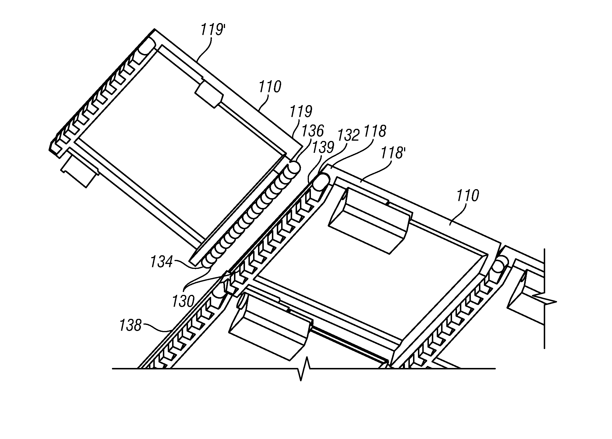
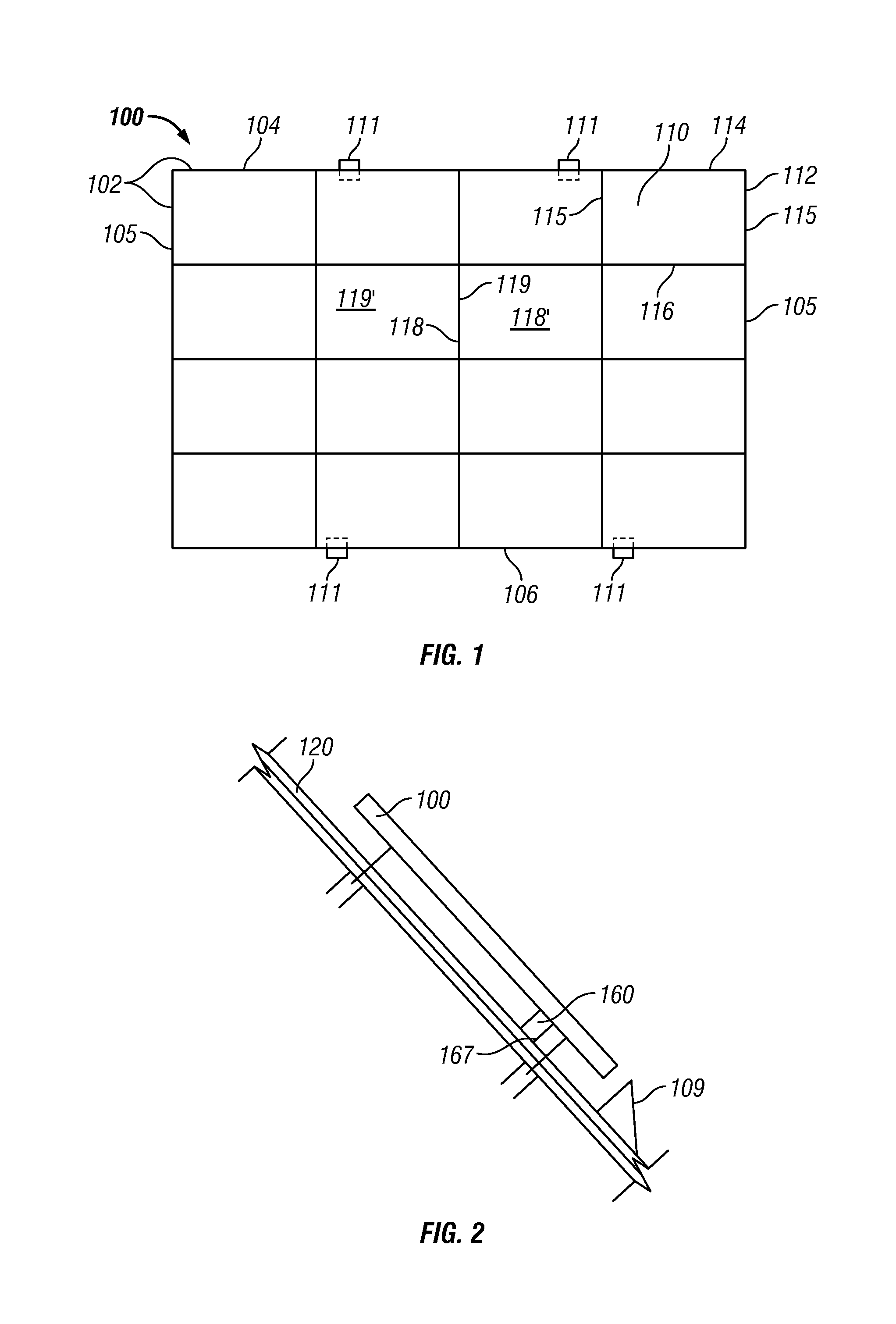
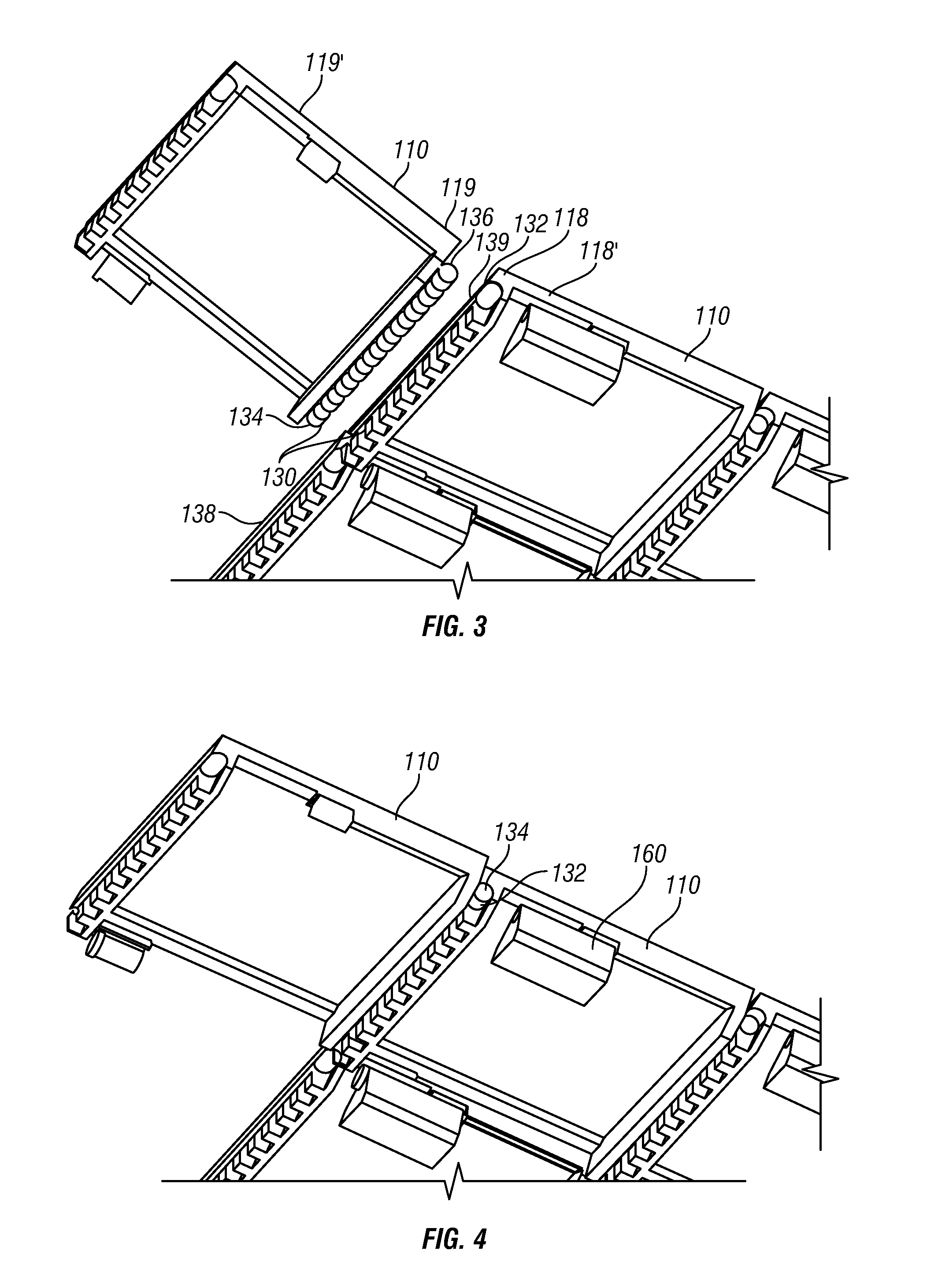
Minimally penetrating photovoltaic assembly for use with a sloped roof and related methods

a photovoltaic assembly and minimal penetration technology, applied in the direction of heat collector mounting/support, pv power plants, light and heating equipment, etc., can solve the problems of difficult installation of pv modules using such traditional rack systems, laborious installation, and difficulty in determining if adequate waterproofing has been achieved

Inactive Publication Date: 2011-09-29
SUNPOWER CORPORATION
View PDF14 Cites 28 Cited by
  • Summary
  • Abstract
  • Description
  • Claims
  • Application Information

AI Technical Summary

Benefits of technology

An assembly includes an interconnected array of photovoltaic (PV) modules, where each of the PV modules is defined in part by a module outer perimeter portion. The array is defined in part by an outer perimeter portion including an upper edge portion, side edge portions, and a lower edge portion. The interconnected array is configured to be secured to a sloped roof along at least one of the upper or lower edge portion of the array. The assembly further includes interlocking features along the module outer perimeter portion which distribute uplift forces to adjacent modules. Additionally included is at least one wind deflector located along the lower edge of the array and one or more non-penetrating base feet are configured to be disposed on the sloped roof, where the base feet supports at least a portion of the interconnected array of PV modules. Wind uplift forces on the array may be resisted through distribution of forces within the array, pressure equalization treatment, and / or aerodynamic treatment of the array.

Problems solved by technology

Installations of PV modules using such traditional rack systems may be difficult because, for example, the installations can be very labor intensive due to the deficient designs of the stanchions and rails.
Additionally, the stanchions may possibly penetrate deeply into the roof and / or in a large number of locations.
Because of the size of these large holes, and / or the large number of penetrations, it is often difficult to tell if adequate waterproofing has been achieved.

Method used


Image

  • Minimally penetrating photovoltaic assembly for use with a sloped roof and related methods
  • Minimally penetrating photovoltaic assembly for use with a sloped roof and related methods
  • Minimally penetrating photovoltaic assembly for use with a sloped roof and related methods

Examples


Embodiment Construction

The following detailed description includes references to the accompanying drawings, which form a part of the detailed description. The drawings show, by way of illustration, specific embodiments in which the present photovoltaic assemblies and methods may be practiced. These embodiments, which are also referred to herein as “examples,” are described in enough detail to enable those skilled in the art to practice the present photovoltaic assemblies and methods. The embodiments may be combined, other embodiments may be utilized or structural or logical changes may be made without departing from the scope of the present photovoltaic assemblies and methods. The following detailed description is, therefore, not to be taken in a limiting sense, and the scope of the present photovoltaic assemblies and methods is defined by the appended claims and their legal equivalents.

In this document, the terms “a” or “an” are used to include one or more than one, and the term “or” is used to refer to ...


PUM

PropertyMeasurementUnit
uplift forcesaaaaaaaaaa
forcesaaaaaaaaaa
perimeteraaaaaaaaaa

Abstract

An assembly which is lightweight includes an interconnected array of PV modules, where each PV modules is defined in part by a module outer perimeter portion. This array is defined in part by an outer perimeter portion including an upper edge portion, side edge portions, and a lower edge portion. The array is secured to a sloped roof along at least one of the upper or lower edge portion of the array. The assembly further includes interlocking features along the module outer perimeter portion which distribute uplift forces to adjacent PV modules. Additionally included is at least one wind deflector located along the lower edge of the array and non-penetrating base feet disposed on the sloped roof supporting at least a portion of the array.

Description

TECHNICAL FIELDThe application relates generally to a photovoltaic array. More particularly, it relates to a minimally penetrating photovoltaic assembly for use with a sloped roof.BACKGROUNDCurrently, photovoltaic (PV) modules can be secured to roofs with rack systems that include vertical stanchions and lateral rails. In particular, the lateral rails are attached to the stanchions, which are typically several inches off the roof, and the PV modules are attached to the rails. Installations of PV modules using such traditional rack systems may be difficult because, for example, the installations can be very labor intensive due to the deficient designs of the stanchions and rails. Additionally, the stanchions may possibly penetrate deeply into the roof and / or in a large number of locations. For example, relatively large holes are often pre-drilled through the roofing material to accommodate the mounting hardware. Because of the size of these large holes, and / or the large number of pen...

Claims


Application Information

Patent Timeline
Patent Type & Authority Applications(United States)
IPC IPC(8): H01L31/042B32B43/00B32B37/02
CPCF24J2/5211F24J2/5262F24J2002/4659F24J2002/4665F24J2002/467H02S20/23Y02B10/12Y02B10/20Y02E10/47F24J2002/5486F24J2002/4672F24S2025/6008F24S2030/16F24S25/20F24S2025/6007F24S2025/6004F24S25/67F24S2025/6001Y02E10/50Y02B10/10
Inventor LENOX, CARL J.S.ROSE, DOUGKNUEPFEL, MICHAEL
Owner SUNPOWER CORPORATION
Why Eureka
Try Eureka