
Eureka
For R&D, Eureka makes reading and utilizing patents & technical documents easy.
Eureka AIR
Designed for self-driven R&D workflows. Generate viable solutions, solve complex R&D challenges, empower your innovation with AI.

Eureka Materials
Designed for material experts only. Revolutionize your material R&D, from search, analyze, to developing new materials.

TechResearch
Generate reliable direction feasibility study reports for your R&D in just a few steps.

TechSeek
Discover and master advanced knowledge NOW. Basics, ideas, possibilities, all at once.

TechMind
As an expert in R&D Theories, TechMind can generates customized viable solutions instantly.

TechRisk
Analyze your overall solution with one click, know your potential R&D risks in advance.

TechMonitor
Get weekly tech updates, stay abreast of the latest tech innovations and key insights.
Power circuit
- Summary
- Abstract
- Description
- Claims
- Application Information
AI Technical Summary
Benefits of technology
Problems solved by technology
Method used
Image

Examples
Embodiment Construction
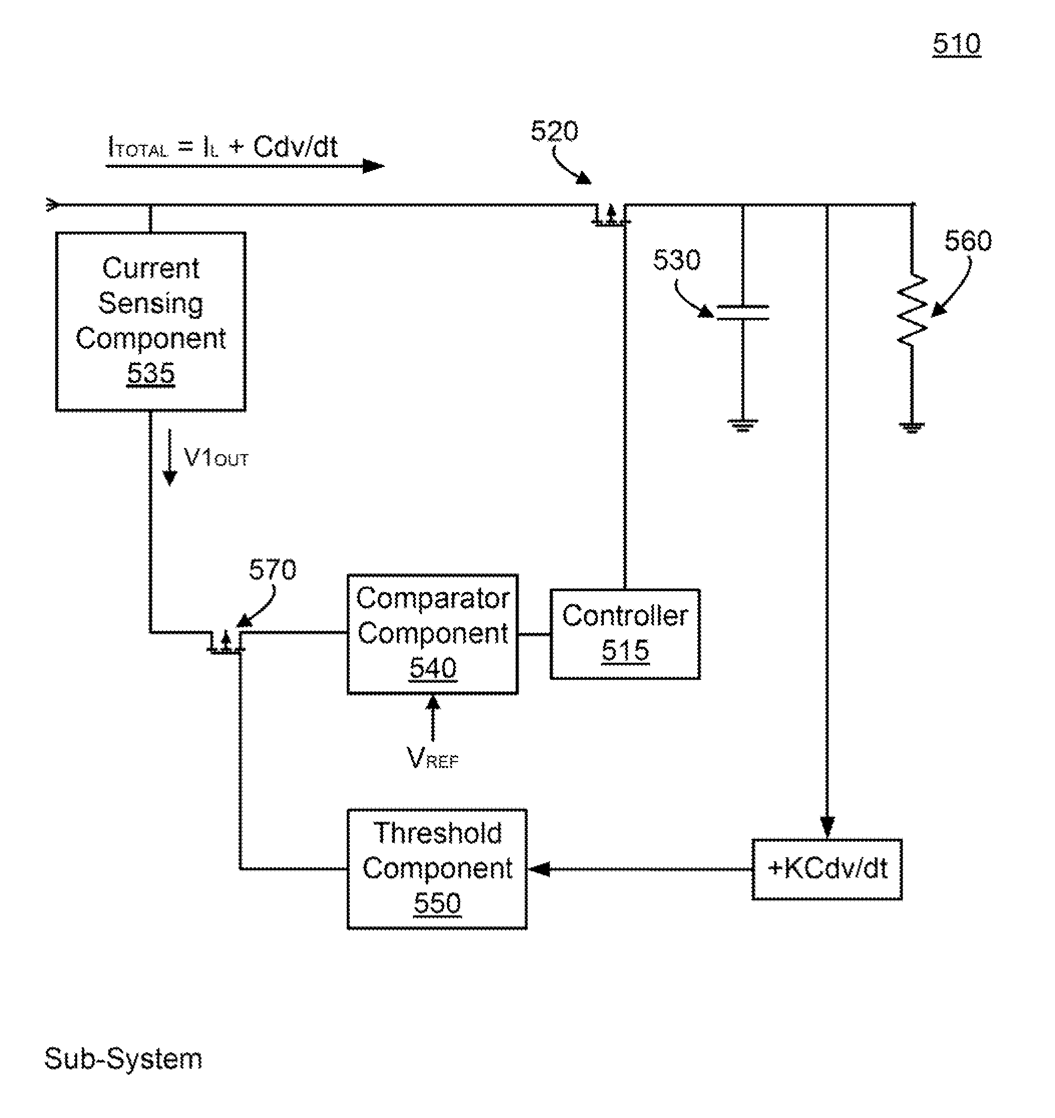
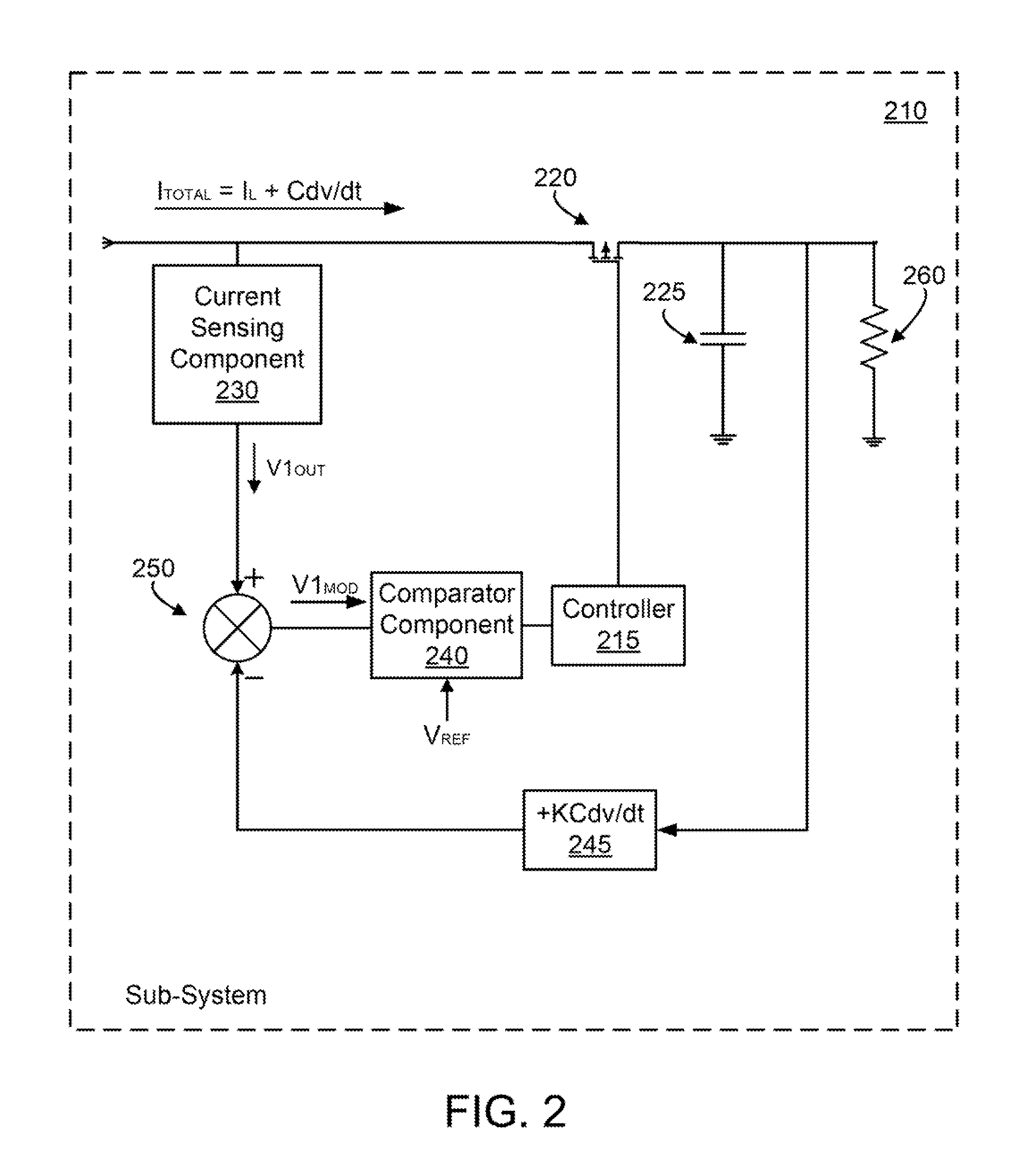
Various embodiments provide systems and methods for controlling sub-system components during power disturbances. More particularly, various embodiments provide a circuit and method for preventing a controller within a sub-system from turning OFF a switching device during power disturbance events related to other sub-systems.
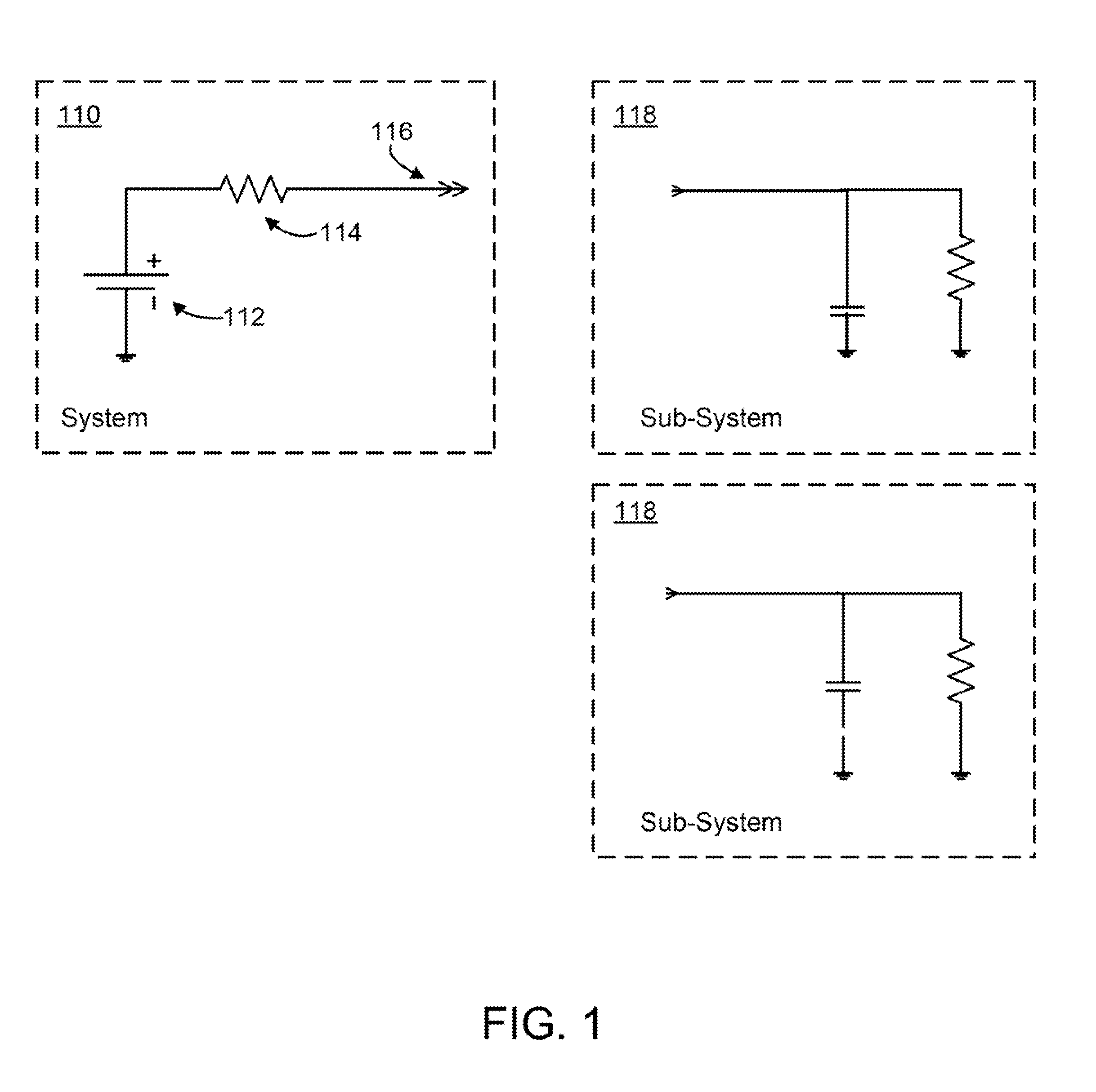
FIG. 1 illustrates an exemplary system 110 of the present application. The system 110 may be a system enclosure, a card cage, a main system, a cabinet, or similar structures. For simplicity purposes, the system is modeled as a Thevenin equivalent comprising a power source 112 and a series resistor 114. However, as one of ordinary skill in the art would readily understand, the system 110 is actually more complex and comprises a plurality of components arranged in a specific manner to interconnect with and provide power to various sub-systems 118. These sub-systems 118 are interconnected with the system 110 via one or more connectors 116. The system 110 is arranged...
PUM
 Abstract
Description
Claims
Application Information
 - R&D Engineer
- R&D Manager
- IP Professional
- Industry Leading Data Capabilities
- Powerful AI technology
- Patent DNA Extraction
Browse by: Latest US Patents, China's latest patents, Technical Efficacy Thesaurus, Application Domain, Technology Topic, Popular Technical Reports.
© 2024 PatSnap. All rights reserved.Legal|Privacy policy|Modern Slavery Act Transparency Statement|Sitemap|About US| Contact US: help@patsnap.com