Method of adjusting an acoustic output from a display device

Inactive Publication Date: 2011-09-29
TP VISION HLDG B V HOLDCO
View PDF14 Cites 3 Cited by
  • Summary
  • Abstract
  • Description
  • Claims
  • Application Information

AI Technical Summary

Benefits of technology

[0004]It is an object to provide a display device which allows different types of mounting and still provides a good sound performance in different types of mounting.
[0011]The display device according to the invention is able to obtain a good sound performance in different mounting situations, e.g. wall-mounting versus stand-mounting, by means of modifying the acoustic output according to the detected type of mounting of the display device. E.g. by means of modifying the electric input to the loudspeaker according to the type of mounting based on predetermined knowledge of the acoustic performance in such different mounting situations. This allows automatic adjustment of the acoustic output to suit the selected type of mounting, such that an overall acceptable sound performance can be obtained without any action of the user. As will be illustrated in the following, this acoustic compensation can be implemented with low cost components e.g. for use in a flat panel TV set with mounting fittings for wall and stand mounting.
[0017]The display may especially be a flat panel display. Such display type are usually mounted in small cabinets providing severe acoustic design limitations, and thus the display device according to the invention is especially relevant for improving sound performance of devices with such display. The display device may be such as a TV set, a computer display, and a beamer device.

Problems solved by technology

It is a well-known problem that acoustical performance of prior art audio systems varies according to the way the system is placed in a room.
Further, on a flat panel TV set the loudspeakers will typically be placed on the side of the cabinet, sometimes even directed away from the listener position, the loudspeaker position being more or less fixed by strong cabinet design requirements which only allow very narrow space for loudspeakers.
Designing a TV set for proper sound performance in one mounting situation will result in poor performance in another mounting situation.
However, even if possible at all, many users are not capable of using such controls properly to obtain a suitable sound performance, and consequently a poor sound performance from the TV set is the result.

Method used


Image

  • Method of adjusting an acoustic output from a display device
  • Method of adjusting an acoustic output from a display device

Examples


Embodiment Construction

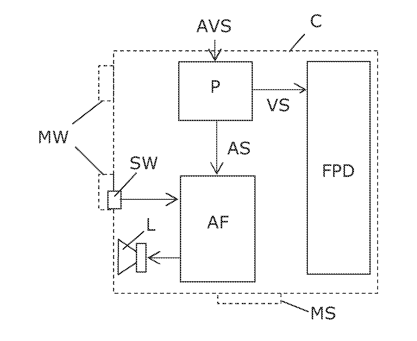
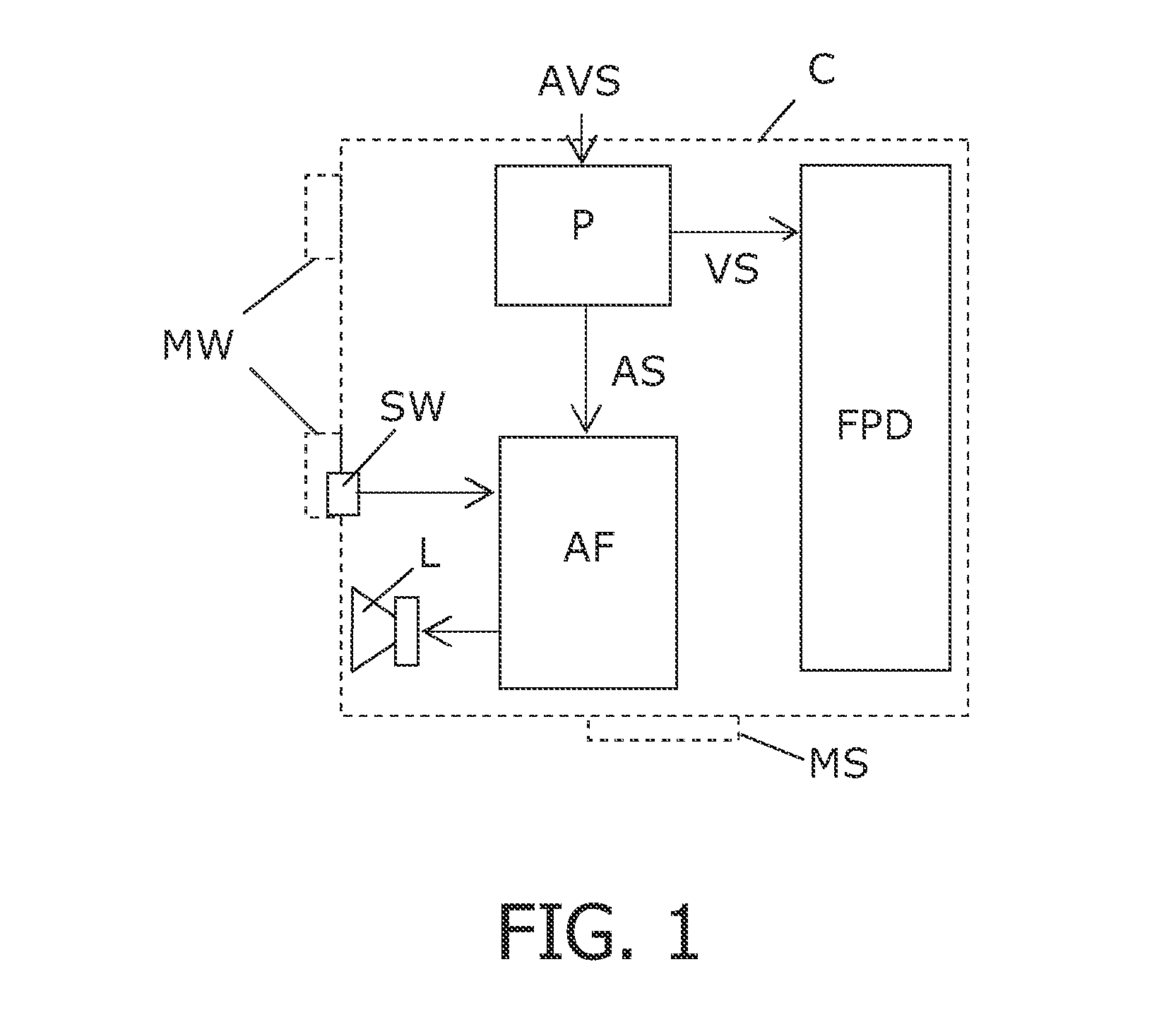
[0022]FIG. 1 illustrates in schematic form one specific display device embodiment. The display device in this embodiment has a flat panel display FPD, such as an LCD display panel, for delivering a visual output in response to an audio-video input signal AVS. The flat panel display is mounted in a cabinet C. Further, the device includes an acoustic system including one or more loudspeakers L. Such acoustic system may include a set of stereo loudspeakers L, e.g. a set of two loudspeakers in a two-way configuration, i.e. each with two loudspeaker drivers connected via a cross-over network to cover the desired audio frequency range. Normally, the loudspeakers L will be mounted in the cabinet, so as to generate an acoustic output from the display device in response to the audio-visual input signal AVS. In case of the acoustic system including a set of stereo loudspeakers L, separate loudspeaker drivers L are typically arranged in the sides of the cabinet C. A processor P receives the au...


PUM


Abstract

A display device arranged generates a visual and an acoustic output according to an input signal (AVS) with audio (AS) and video (VS) content. The display device includes a cabinet (C) with different mounting fittings (MS, MW) arranged for different types of mounting of the display device. A display (FPD), an acoustic system including one or more loudspeakers (L), a mounting detector (SW), e.g. a microswitch, arranged to detect a type of mounting of the display device, and compensation means (AF) arranged to modify the acoustic output from the display device according to the detected type of mounting of the display device. Hereby, it is possible to adjust the frequency content of the acoustic output from the acoustic system, e.g. electronically, to correspond to the acoustic environment determined by means of sensing the type of mounting of the display device. E.g. one microswitch can be used to discriminate between wall or stand mounting, and digital coefficients for an IIR or an FIR filter can be selected accordingly to compensate the acoustic output from the display device to a desired response. Hereby sound performance of especially flat panel display devices can be improved, since such devices typically exhibit an audio performance which is highly depending on the type of mounting due.

Description

FIELD OF THE INVENTION[0001]The present invention relates to a method of adjusting an acoustic output from a display device. The invention also relates to a display device arranged to carry out such a method.BACKGROUND OF THE INVENTION[0002]It is a well-known problem that acoustical performance of prior art audio systems varies according to the way the system is placed in a room. A loudspeaker placed close against a wall will produce significantly more bass output than the same loudspeaker placed away from walls. The same also applies to devices with built-in loudspeakers such as flat panel TV sets. Such TV sets are typically either placed on a surface or hang on the wall, i.e. two different mountings seen from an acoustic point of view. Further, on a flat panel TV set the loudspeakers will typically be placed on the side of the cabinet, sometimes even directed away from the listener position, the loudspeaker position being more or less fixed by strong cabinet design requirements wh...

Claims


Application Information

Patent Timeline
IPC IPC(8): H04R9/06
CPCH04R5/02H04R1/026H04R1/02H04R3/00H04N5/60
Inventor MELS, FRANK KAMIEL IRENAGOUWY, CHRISTIAAN MICHEL WILLY
Owner TP VISION HLDG B V HOLDCO
Why Eureka
Try Eureka