Check patentability & draft patents in minutes with Patsnap Eureka AI!

Determining Points of Parabolic Curvature on Surfaces of Specular Objects

Inactive Publication Date: 2011-09-29
MITSUBISHI ELECTRIC RES LAB INC
View PDF2 Cites 3 Cited by
  • Summary
  • Abstract
  • Description
  • Claims
  • Application Information

AI Technical Summary

Problems solved by technology

But specular object, i.e., the object having surface with mirror-like reflectance, does not have an appearance of its own, but rather present a distorted view of an environment surrounding the object.
Therefore, identifying the point correspondences using an image feature descriptor of the specular object is challenging.

Method used


Image

  • Determining Points of Parabolic Curvature on Surfaces of Specular Objects
  • Determining Points of Parabolic Curvature on Surfaces of Specular Objects
  • Determining Points of Parabolic Curvature on Surfaces of Specular Objects

Examples


Embodiment Construction

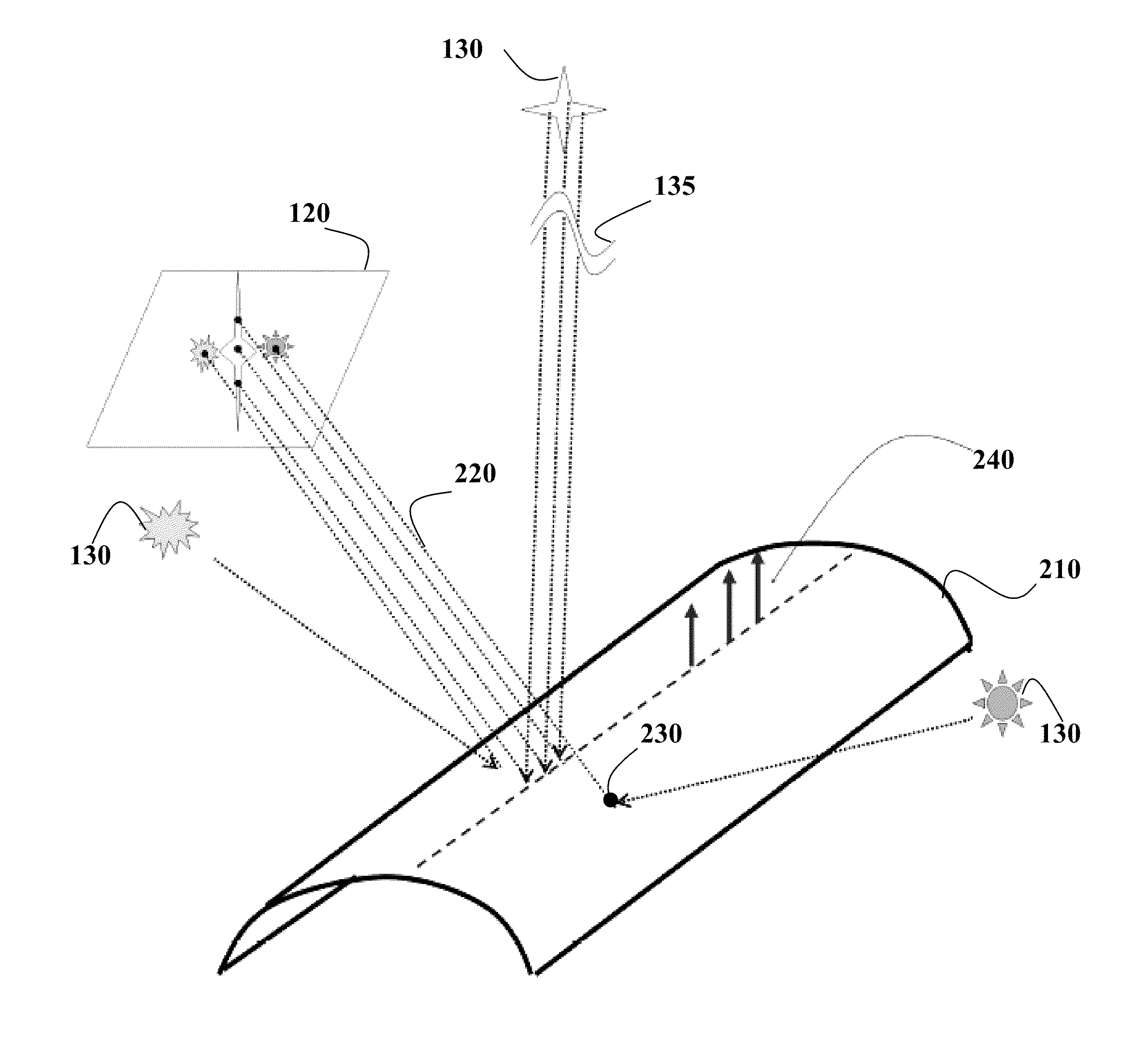
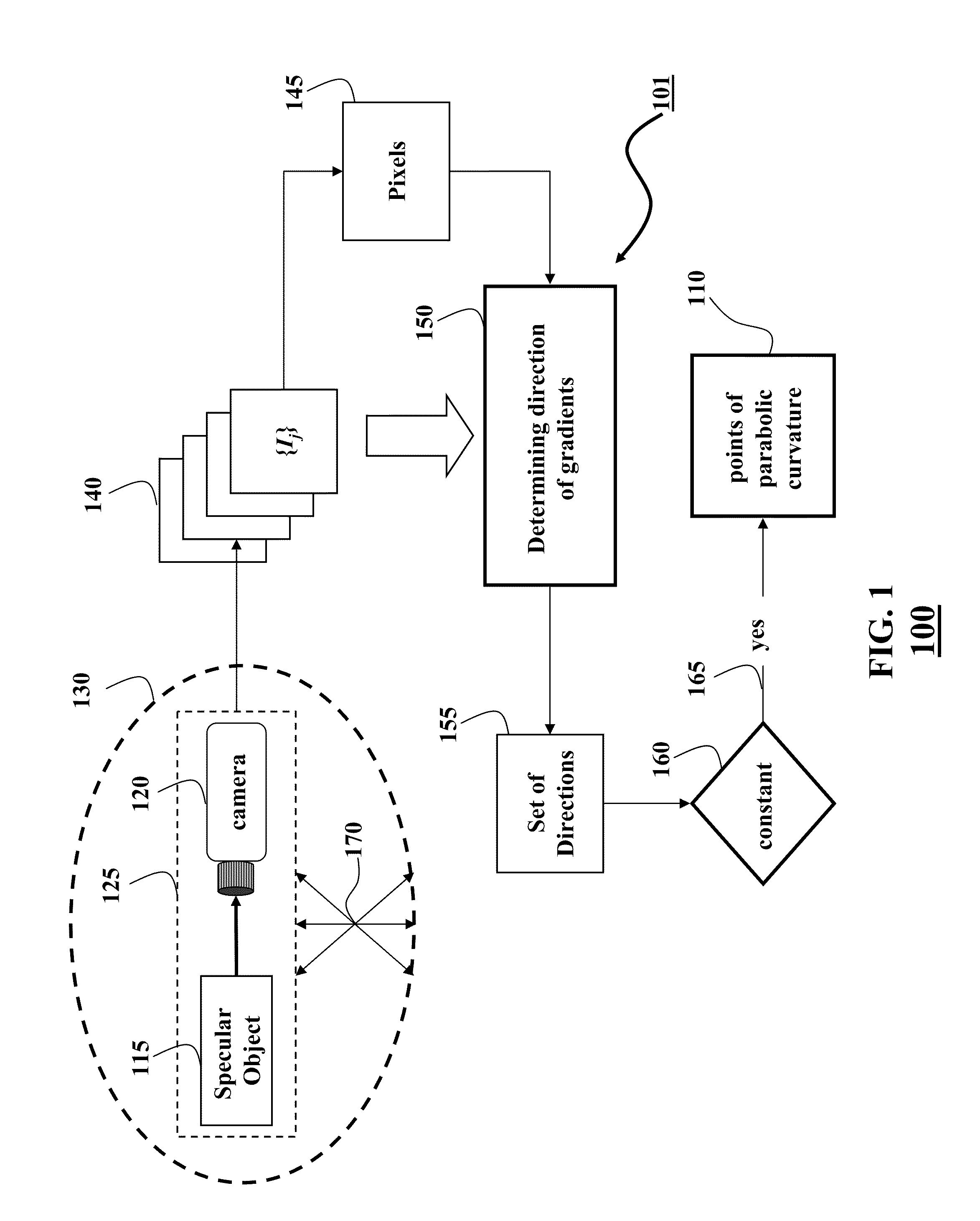
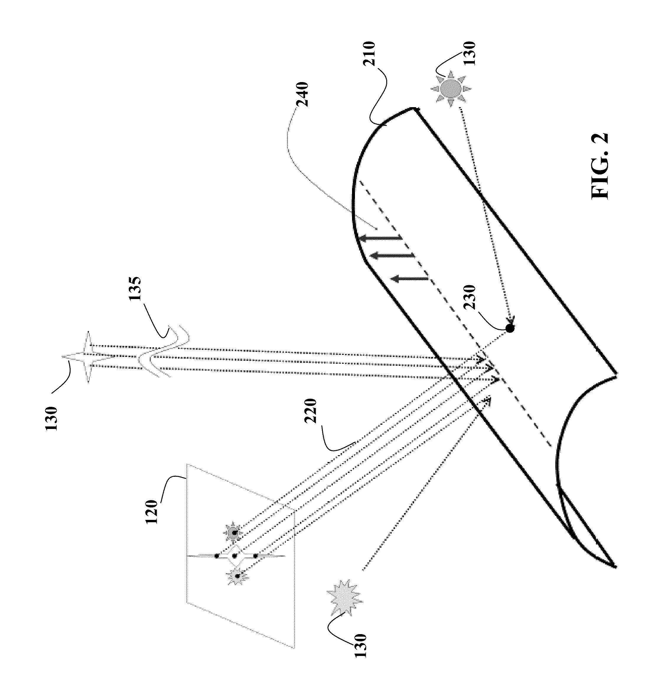
[0020]FIG. 1 shows a method 100 for determining points 110 of parabolic curvature on the surface of an object 115 arranged in an environment 130. The object is a specular object having a parabolic curvature of the surface. The points of parabolic curvature are the points of a surface, wherein the surface has no bending (curvature) along only one direction. For example, if the object is a cylinder, the surface of the cylinder is formed by the points at a fixed distance from an axis of the cylinder. The surface of the cylinder curves in the direction, e.g., perpendicular to the axis. However, the surface has no bending in the direction parallel to the axis along a height of the cylinder. Example of the points 310 of parabolic curvature of the surface 320 is shown in FIG. 3A.

[0021]The points of parabolic curvature are determined based on a set 140 of images {Ij} of the object acquired by a camera 120 under a relative motion 170 between a camera-object pair 125, and the environment. In ...


PUM


Abstract

Embodiments of the invention disclose a system and a method for determining points of parabolic curvature on a surface of a specular object from a set of images of the object is acquired by a camera under a relative motion between a camera-object pair and the environment. The method determines directions of image gradients at each pixel of each image in the set of images, wherein pixels from different images corresponding to an identical point on the surface of the object form corresponding pixels. The corresponding pixels having substantially constant the direction of the image gradients are selected as pixels representing points of the parabolic curvature.

Description

FIELD OF THE INVENTION[0001]This invention relates generally to determining points of parabolic curvature, and more particularly to determining points of parabolic curvature on surfaces of specular objects.BACKGROUND OF THE INVENTION[0002]Image invariants are properties of images of an object that remain unchanged with changes in parameters of a camera and / or illumination. For example, geometric invariants are related to apparent size of different parts of objects and are therefore equally valid for the objects with any reflectance characteristics of the surface, including diffuse, specular and transparent objects. However, in order to use the geometric invariants from the images of the object, point correspondences across the images should be identified. Identifying the point correspondences from images of the diffuse object is a meaningful task since the diffuse object has photometric features. But specular object, i.e., the object having surface with mirror-like reflectance, does...

Claims


Application Information

Patent Timeline
IPC IPC(8): G06K9/46G06V10/60
CPCG06K9/4661G06T2207/10016G06T7/604G06T7/64G06V10/60
Inventor VEERARAGHAVAN, ASHOKTUZEL, ONCEL C.SANKARANARAYANAN, ASWINAGRAWAL, AMIT K.
Owner MITSUBISHI ELECTRIC RES LAB INC
Features
  • R&D
  • Intellectual Property
  • Life Sciences
  • Materials
  • Tech Scout
  • Unparalleled Data Quality
  • Higher Quality Content
  • 60% Fewer Hallucinations
Learn More