Transfer ring for offset tapered 3D connector

a technology of transfer rings and connectors, applied in the field of orthopaedic implant systems, can solve the problems of spinal fastener back-out in some spinal systems, and the performance of implants may be lessened, and achieve the effect of reducing the degree of back-out of spinal fasteners

Active Publication Date: 2005-10-20
WARSAW ORTHOPEDIC INC
View PDF15 Cites 180 Cited by
  • Summary
  • Abstract
  • Description
  • Claims
  • Application Information

AI Technical Summary

Problems solved by technology

Under some conditions, a degree of back-out of the spinal fasteners can occur in some spinal systems after installation.
In other cases, however, performance of the implants may be lessened, and additional surgery may be necessary to secure or replace implant parts.

Method used


Image

  • Transfer ring for offset tapered 3D connector
  • Transfer ring for offset tapered 3D connector
  • Transfer ring for offset tapered 3D connector

Examples


Embodiment Construction

[0012] For the purposes of promoting an understanding of the principles of the invention, reference will now be made to the embodiments illustrated in the drawings and specific language will be used to describe the same. It will nevertheless be understood that no limitation of the scope of the invention is thereby intended, such alterations, modifications, and further applications of the principles of the present invention as illustrated being contemplated as would normally occur to one skilled in the art to which the invention relates.

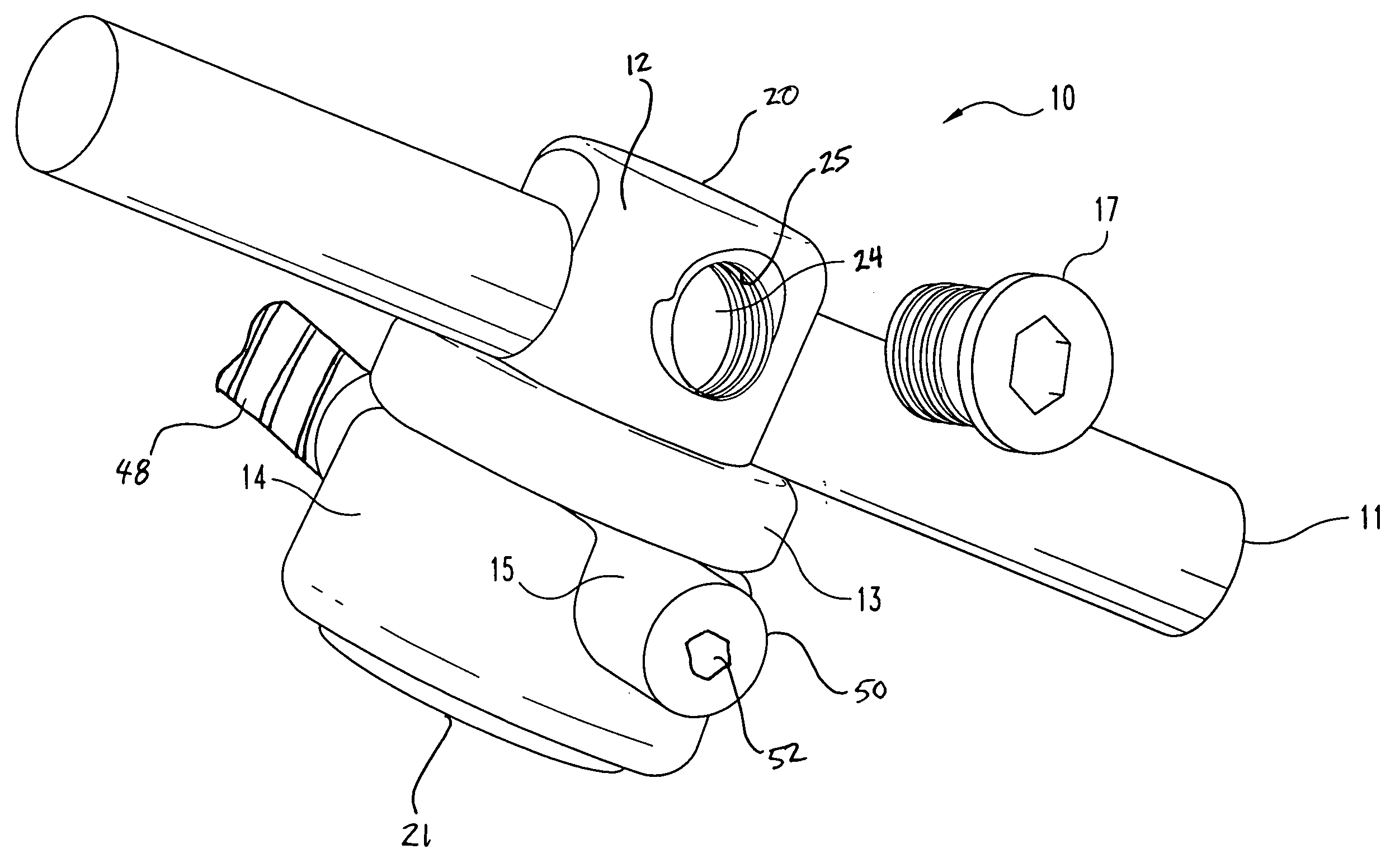
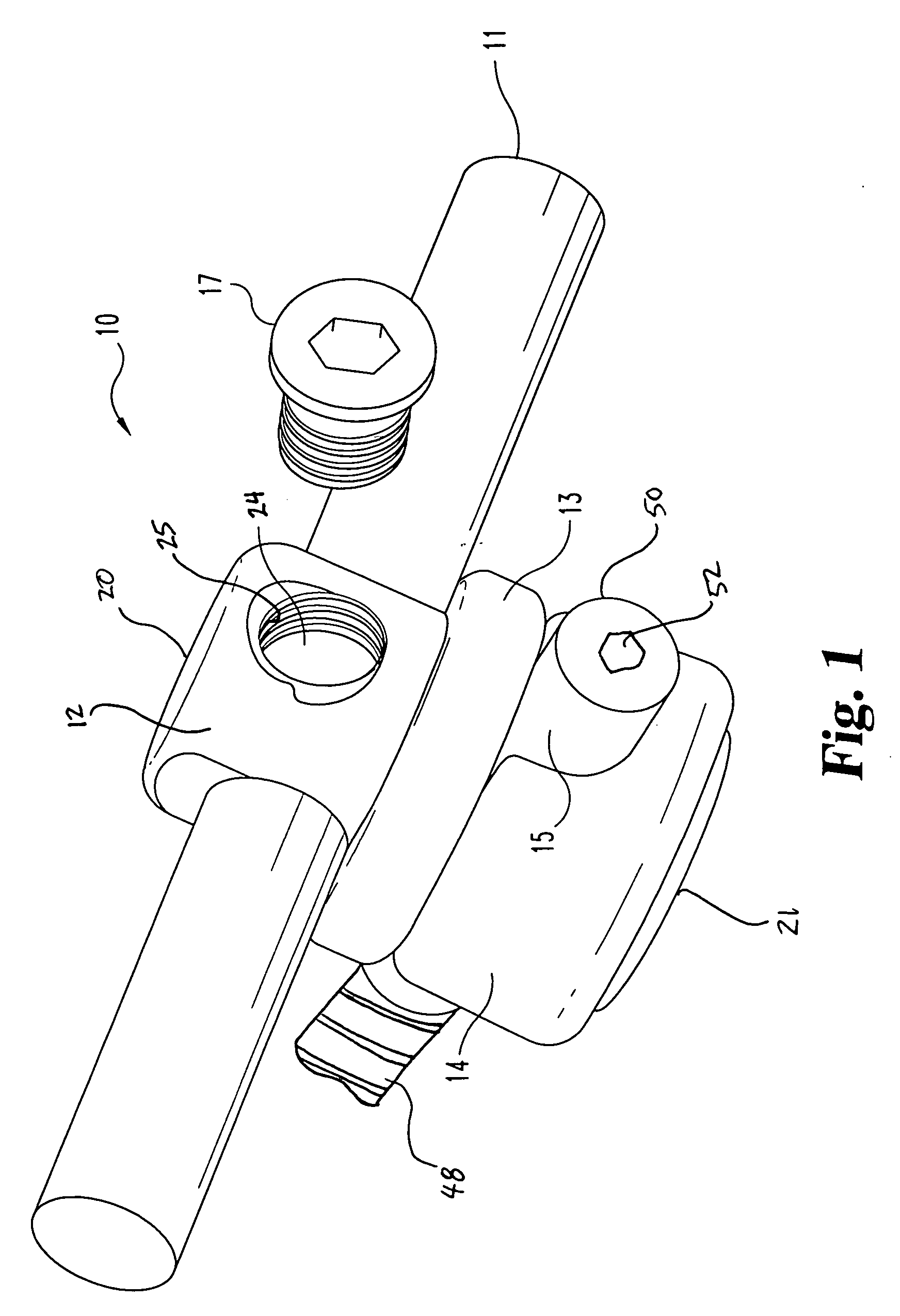
[0013] In accordance with one embodiment of the present invention, FIG. 1 shows a connection device 10 for connecting an elongated member 11 and a bone fixation member 15 together. This embodiment will be described in the context of a spinal usage, although other usages for this and other embodiments may be possible. This embodiment of connection device 10 includes an offset body 12, offsetting member 13, and washer 14. Elongated member 11 and bone f...


PUM


Abstract

Embodiments of a device and method for connecting a bone fastener, for example a spinal screw, to an elongated member are disclosed. In one embodiment, a body having channels to receive the fastener and elongated member is tapered and has an aperture for a locking member. A tapered washer slides over the body. The tapered washer has an inner diameter that is smaller than part of the tapered portion of the body allowing it to engage the body. The fastener passes through the body and engages the washer. An offsetting member slides over the body. The body slides over the elongated member and the offsetting member offsets the elongated member from the spinal fastener and contacts each in two differing locations. A locking member is inserted into a threaded aperture in the body to apply a compressive force that compresses all of the members preventing relative motion of the components.

Description

FIELD OF THE INVENTION [0001] This invention relates generally to the field of orthopedic implant systems, particularly to systems of the type that employ fasteners engaged to elongated members. More particularly, the invention concerns a connector that provides variable angle adjustability between a fastening element and the elongated member while allowing ease of assembly. BACKGROUND OF THE INVENTION [0002] Several systems have been developed for the use in correcting and stabilizing orthopedic injuries or deformities and promoting bone fusion. For example, in systems intended for the spine, an elongated member, commonly in the form of a bendable rod, can be longitudinally disposed adjacent the vertebral column and is fixed to various vertebrae along the length of the column by way of a number of spinal fasteners. A variety of spinal fasteners can be used, such as hooks, bone bolts and screws, each configured to engage a specific portion of the vertebrae. [0003] An example of a sp...

Claims


Application Information

Patent Timeline
Patent Type & Authority Applications(United States)
IPC IPC(8): A61B17/56A61B17/70
CPCA61B17/7037A61B17/7041A61B17/7038
Inventor BARKER, B. THOMAS
Owner WARSAW ORTHOPEDIC INC
Why Eureka
Try Eureka