Retaining wall block system

a technology of retaining wall blocks and blocks, applied in the direction of excavation, foundation engineering, artificial islands, etc., can solve the problems of limit their performance, add significant expense to the cost, and add to the cost of walls

Inactive Publication Date: 2011-10-06
KEYSTONE RETAINING WALL SYST
View PDF13 Cites 61 Cited by
  • Summary
  • Abstract
  • Description
  • Claims
  • Application Information

AI Technical Summary

Problems solved by technology

There are limits to their performance however, particularly at the upper portions of the wall, where the load of the blocks above the geogrids layer do not provide as much load on the connection, so that frictional forces are reduced.
The use of frictional connections forces the wall designer and builder to use more and higher strength geogrids because connection strength limits the strength of the system, and this adds expense to the wall.
The difficulty with this approach is that in order for such connectors and retaining mechanisms to provide high levels of efficient connection they must add considerable expense to the cost of using the geogrids reinforcement, and add complexity and expense to the installation process.

Method used


Image

  • Retaining wall block system
  • Retaining wall block system
  • Retaining wall block system

Examples


Embodiment Construction

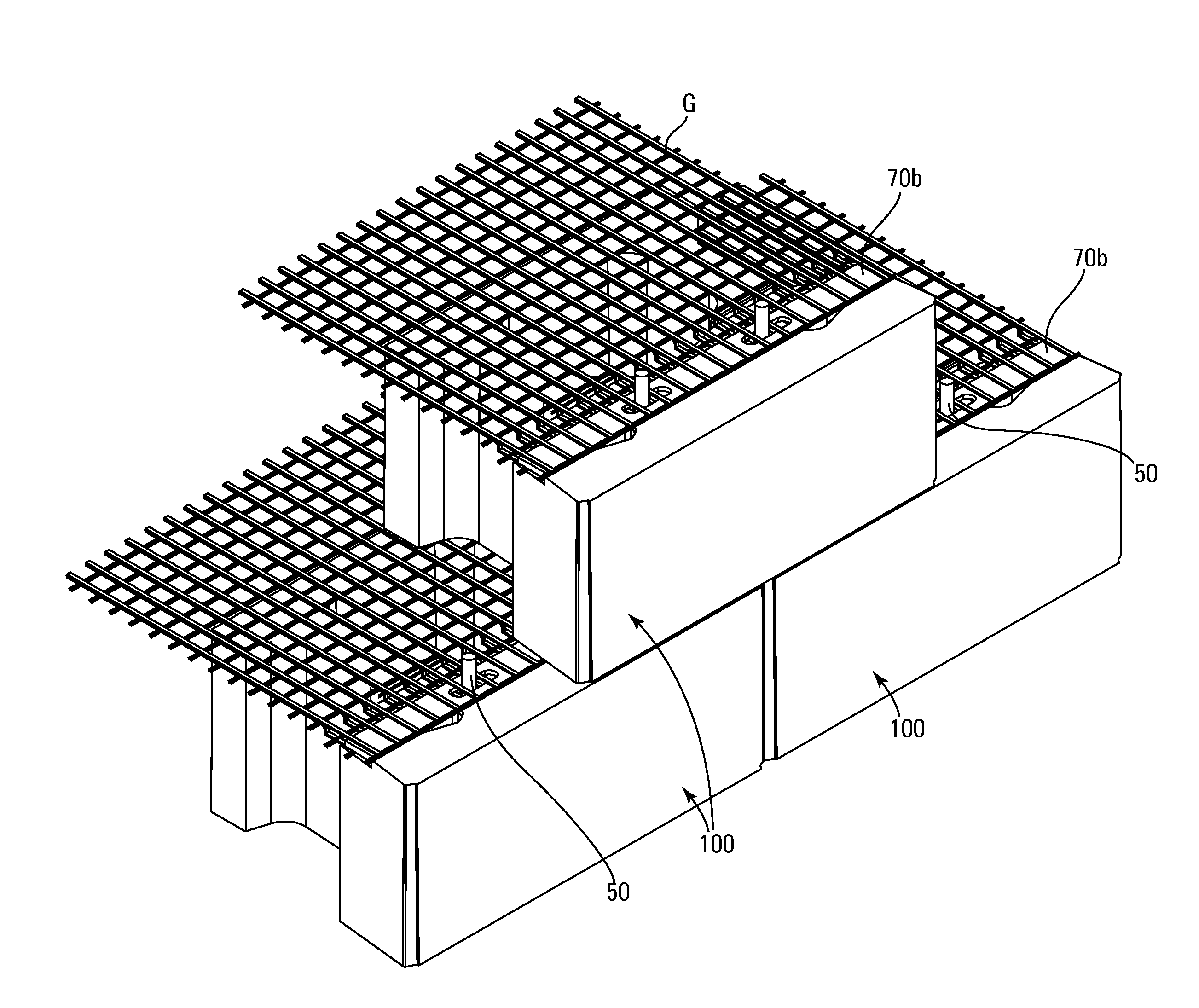
[0040]In this application, “upper” and “lower” refer to the placement of the block in a retaining wall. The lower surface faces down, that is, it is placed such that it faces the ground. In forming a retaining wall, one row of blocks is laid down, forming a course. A second course is laid on top of this by positioning the lower surface of one block on the upper surface of another block.

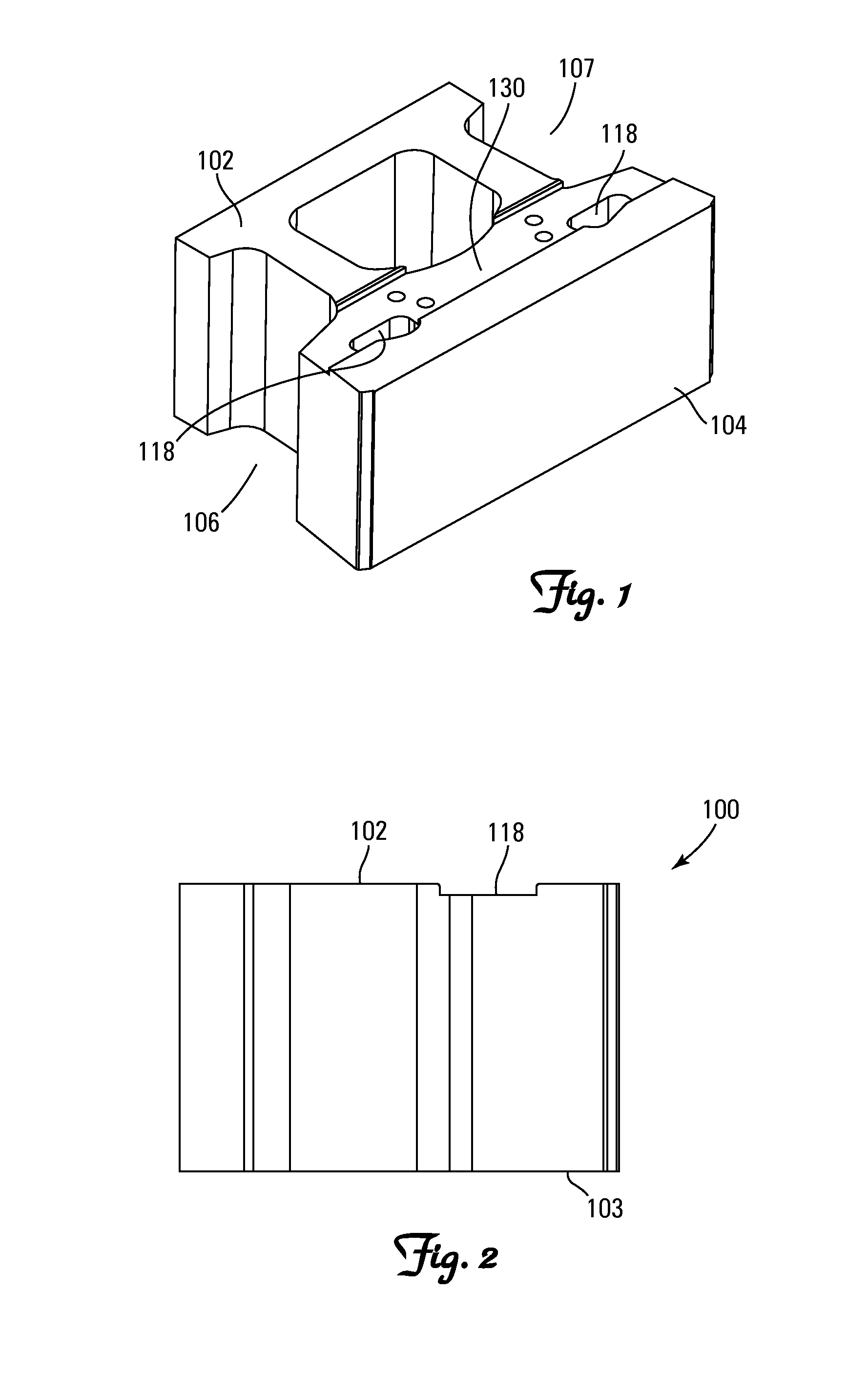
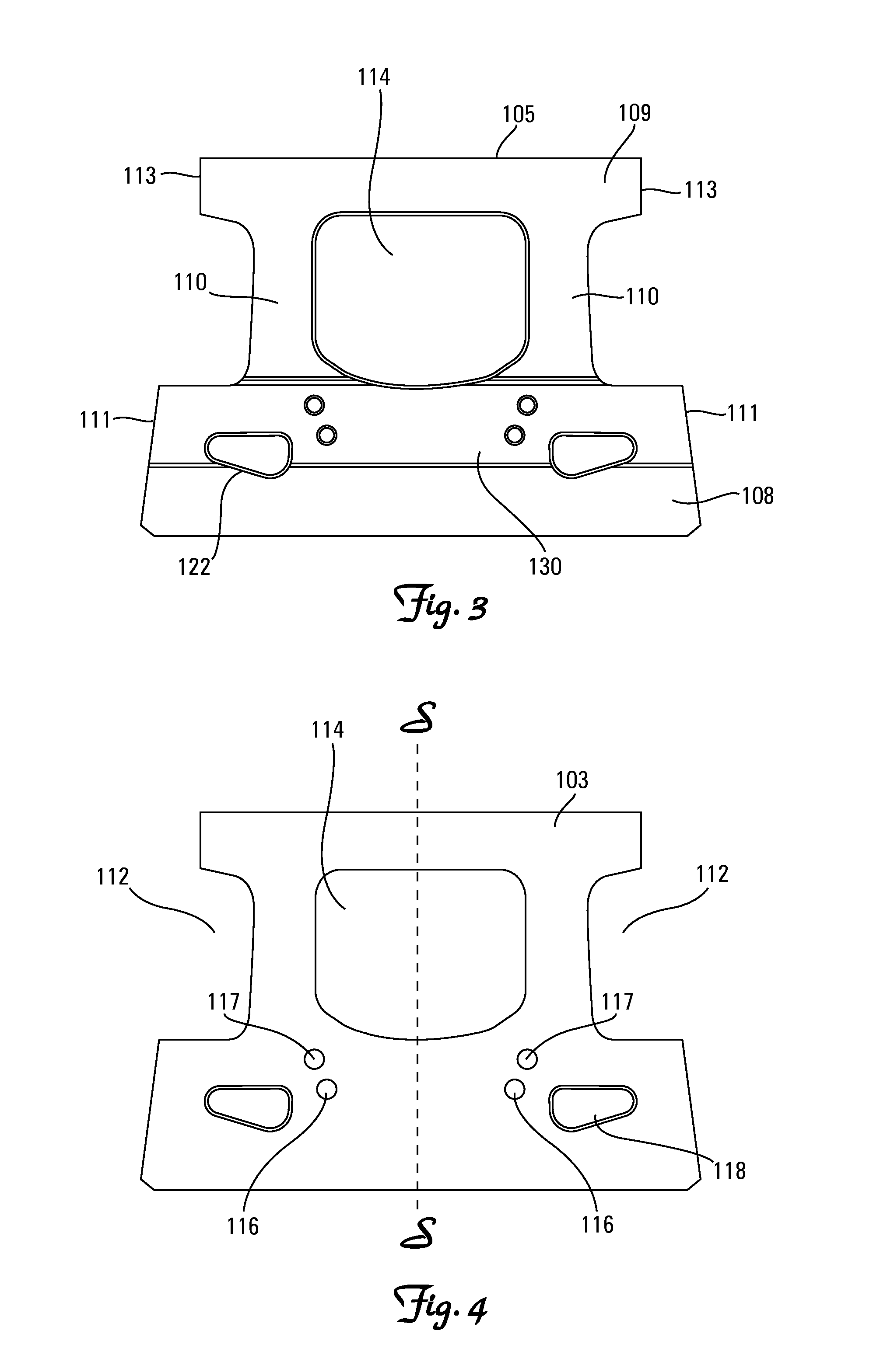
[0041]The blocks of this invention are described and shown as being symmetrical about a vertical plane of symmetry. However, the features of this invention may also be incorporated into blocks that are asymmetrical. The blocks are provided with pin holes, pin receiving cavities, and at least one core which serve to decrease the weight of the block while maintaining its strength while also providing ease of construction of a retaining wall. The blocks are also provided with one or more receiving channels. The location, shape, and size of the pin holes, pin receiving cavities and receiving channels are ...


PUM


Abstract

A wall block having a block body having opposed front and back faces, opposed first and second side walls, and opposed and substantially parallel top and bottom faces, the top face having a receiving channel, and the receiving channel opening onto one or more pin holes. The wall block can be used in a retaining wall made of (i) a plurality of blocks including at least one lower course and at least one upper course, at least one block comprising a block body having opposed front and back faces, opposed first and second side walls, and opposed and substantially parallel top and bottom faces, the top face having a receiving channel, and the receiving channel opening onto one or more pin holes; (ii) a soil retaining material; and (iii) a channel bar.

Description

[0001]This application claims the benefit of U.S. Provisional Patent Application No. 61 / 310,466, filed Mar. 4, 2010, entitled “Retaining Wall Block System”, the contents of which are hereby incorporated by reference herein.FIELD OF THE INVENTION[0002]The present invention relates to retaining wall blocks and walls made from such blocks. In particular, this invention relates to retaining wall blocks having a pinning system and channel bar that can be used with soil reinforcement material, such as a geogrid and walls made therefrom.BACKGROUND OF THE INVENTION[0003]Numerous methods and materials exist for the construction of retaining walls. Such methods include the use of natural stone, poured in-place concrete, pre-cast concrete, masonry, and landscape timbers or railroad ties. In recent years, segmental concrete retaining wall units which are dry stacked (i.e., built without the use of mortar) have become a widely accepted product for the construction of retaining walls. Examples of...

Claims


Application Information

Patent Timeline
Patent Type & Authority Applications(United States)
IPC IPC(8): E02D17/00E04C2/04
CPCE02D29/025E02D29/0266E02D29/0233E02D29/0225E02D29/02
Inventor FRIEDERICHS, JOSEPH M.MORITZ, CRAIG D.
Owner KEYSTONE RETAINING WALL SYST
Why Eureka
Try Eureka