Zero-knowledge proof system, zero-knowledge proof device, zero-knowledge verification device, zero-knowledge proof method and program therefor

a technology of zero-knowledge and proof system, applied in the field of discretelogarithm zero-knowledge proof system, can solve the problems of time-consuming and complicated processing

Inactive Publication Date: 2011-10-06
NEC CORP
View PDF9 Cites 21 Cited by
  • Summary
  • Abstract
  • Description
  • Claims
  • Application Information

AI Technical Summary

Benefits of technology

[0021]As described above, the present invention is structured to perform the calculation processing for calculating the hash values while re-utilizing the memory that stores the pseudorandom number and the hash values. Therefore, it is unneces

Problems solved by technology

Therefore, the processing become

Method used


Image

  • Zero-knowledge proof system, zero-knowledge proof device, zero-knowledge verification device, zero-knowledge proof method and program therefor
  • Zero-knowledge proof system, zero-knowledge proof device, zero-knowledge verification device, zero-knowledge proof method and program therefor
  • Zero-knowledge proof system, zero-knowledge proof device, zero-knowledge verification device, zero-knowledge proof method and program therefor

Examples


first embodiment

[0032]Hereinafter, structures of embodiments of the present invention will be described by referring to the accompanying drawings.

[0033]The basic contents of the embodiment will be described first, and more specific contents thereof will be described thereafter.

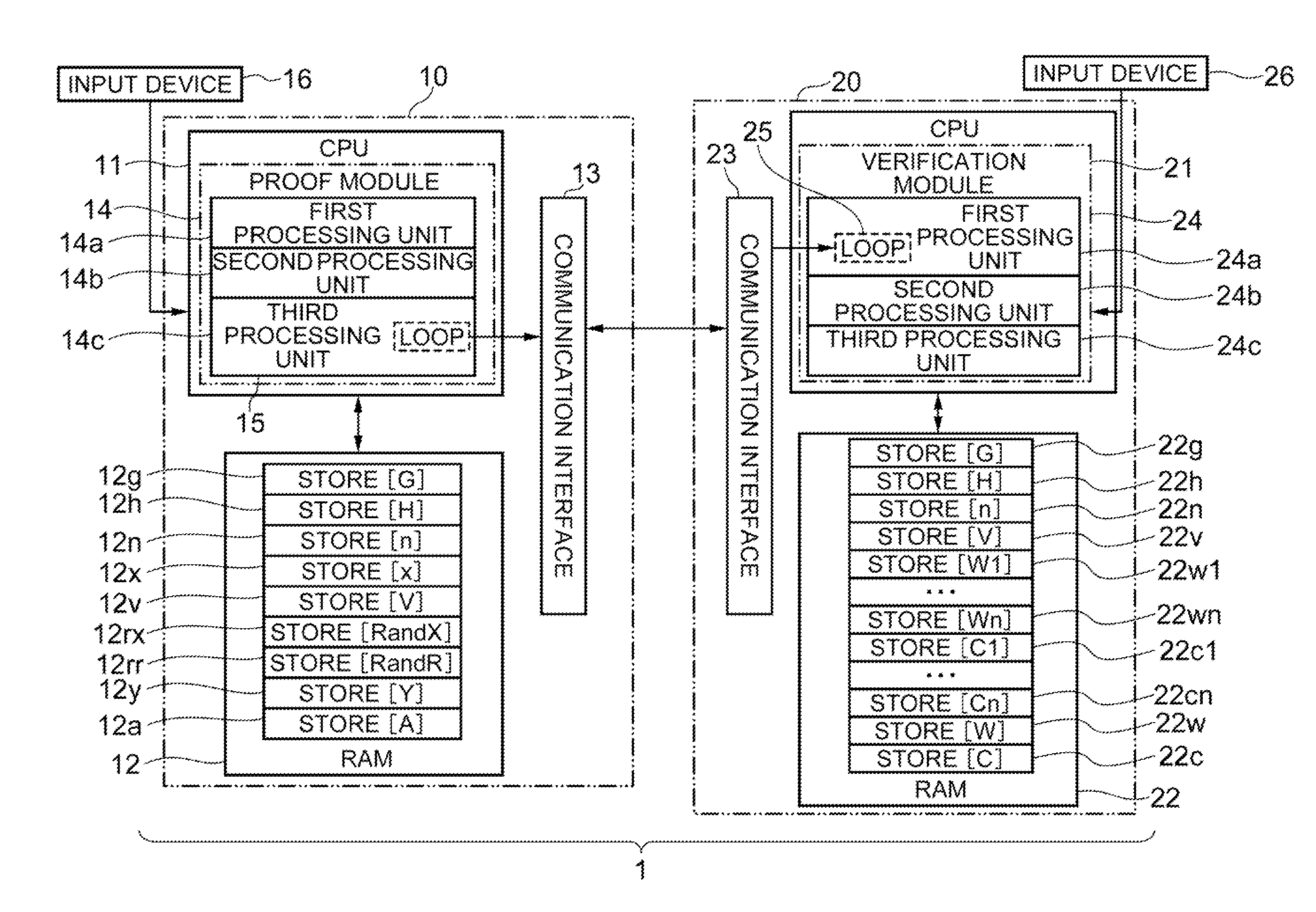
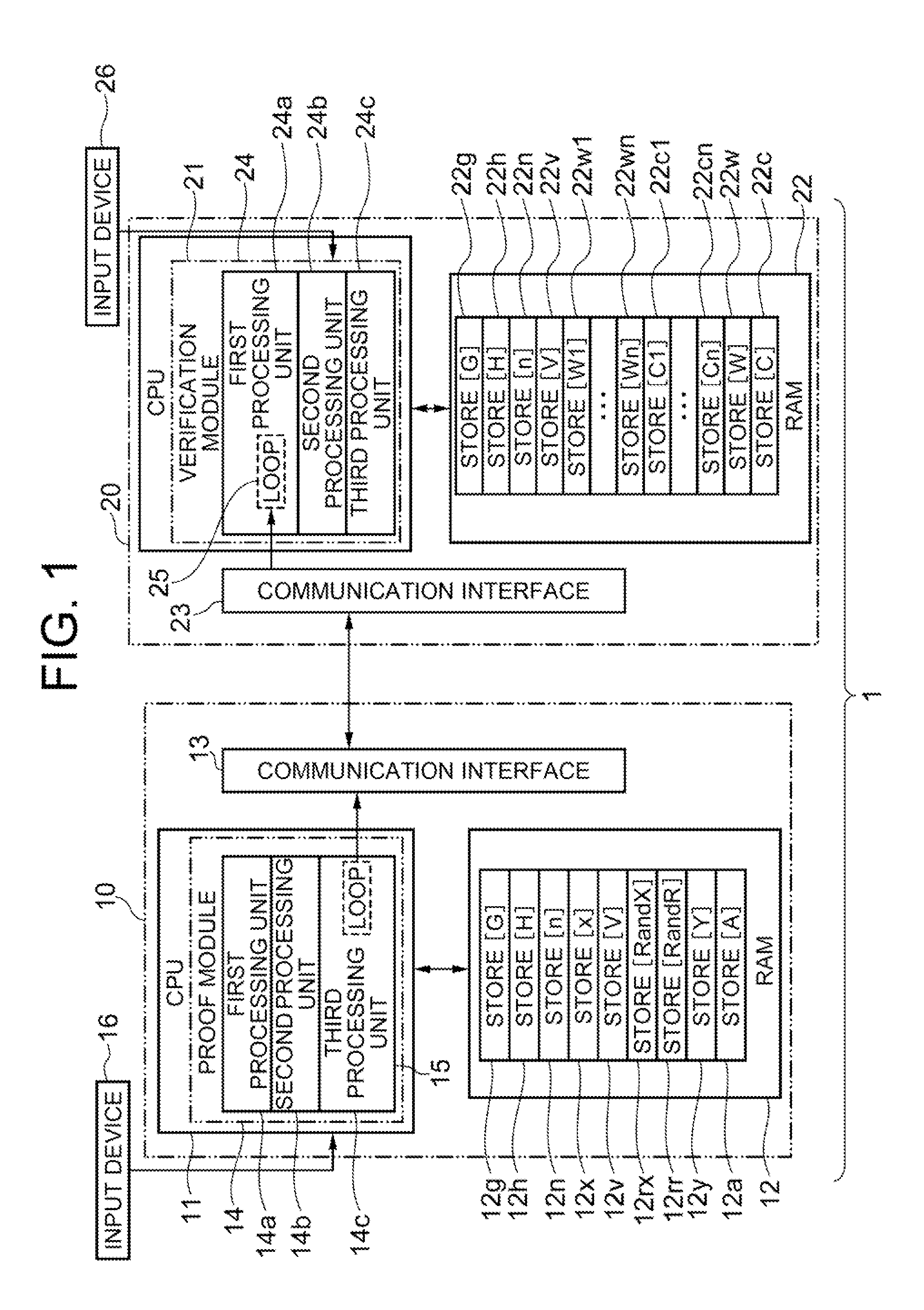
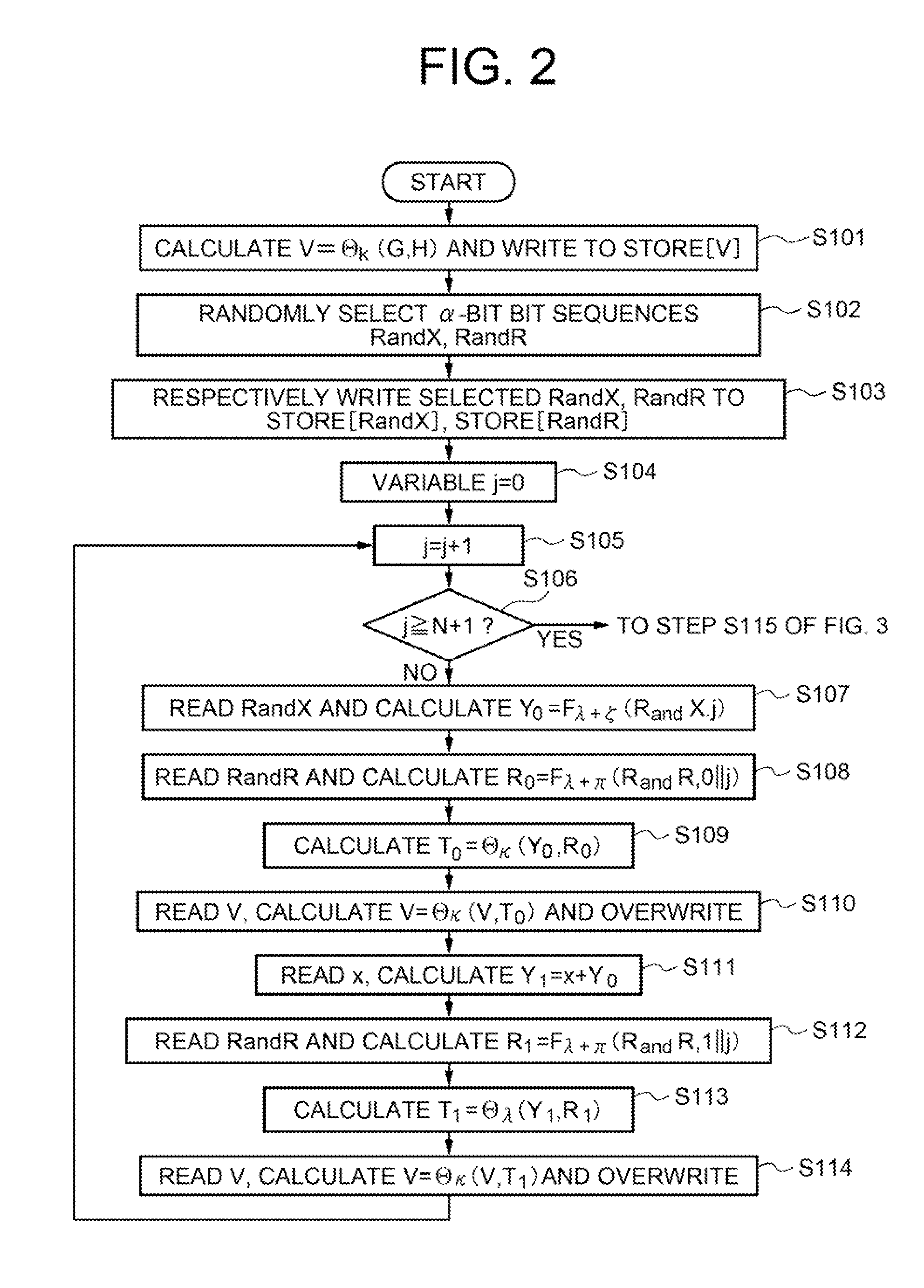
[0034]A zero-knowledge proof system 1 according to the embodiment is constituted with a zero-knowledge proof device (prover device 10) and a zero-knowledge verification device (verifier device 20). The zero-knowledge proof device (prover device 10) includes: a temporary memory unit (RAM 12) which stores pseudorandom numbers and hash values acquired in the past; a first processing unit 14a which calculates a plurality of pseudorandom numbers from an arbitrary random number sequence and a pseudorandom function, and performs a plurality of iterations of processing to calculate hash values based on the calculated pseudorandom numbers and information stored in the temporary memory unit and to overwrite the calculated pseudorandom ...

second embodiment

[0110]Structures of a network, hardware, and a rough structure of software according to a second embodiment of the present invention are the same as those of the first embodiment described by referring to FIG. 1 to FIG. 7. The different points of the second embodiment with respect to the first embodiment described above are that the zero-knowledge proof device (prover device 10) includes a first storage device (storage 317) which collectively stores and outputs sets of pseudorandom numbers and hash values outputted to the zero-knowledge verification device (verifier device 20), and that the zero-proof verification device (verifier device 20) includes a second storage device (storage 327) which collectively stores the sets of the pseudorandom numbers and hash values received at the date receiving module from the zero-knowledge proof device (prover device 10).

[0111]The storage device has a larger storage capacity per unit price compared to a volatile storage module, so that it is easy...


PUM


Abstract

Provided is a zero-knowledge proof system that allows a discrete-logarithm zero-knowledge proof. The zero-knowledge proof device includes a temporary memory unit that stores pseudorandom numbers and previously determined hash values, a first processing unit that calculates multiple pseudorandom numbers and performs multiple iterations of processing to calculate hash values based on the calculated pseudorandom numbers and the information stored in the temporary memory unit, a second processing unit that determines some of the multiple pseudorandom numbers based on the hash values, and a third processing unit that re-calculates some of the pseudorandom numbers and sends the hash values obtained to a zero-knowledge verification device. The zero-knowledge verification device includes a temporary memory region, a data receiving module that sequentially receives new input data, and a processing module that overwrites hash values including variables and input data, as variables into the temporary memory region each time the input data are received.

Description

TECHNICAL FIELD[0001]The present invention relates to a discrete-logarithm zero-knowledge proof system. More specifically, the present invention relates to a zero-knowledge proof system, a zero-knowledge proof device, a zero-knowledge verification device, a zero-knowledge proof method and a program therefore, which can decrease a device storage capacity required for zero-knowledge proofs.BACKGROUND ART[0002]First, the discrete-logarithm zero-knowledge proof will be described. The discrete-logarithm zero-knowledge proof herein is a technique used when a prover as an entity (element) proves to a verifier as an entity a fact that “the prover knows x that satisfies H=Gx” without revealing x.[0003]Note here that n is a natural number, G is an element for Z / nZ, and x is an integer. Further, in the lines other than numerical expressions, “G to the power of x” is expressed as “Gx”. This technique is utilized greatly in techniques related to cryptography, and applied in various scenes such a...

Claims


Application Information

Patent Timeline
IPC IPC(8): H04L9/32
CPCH04L9/3013H04L9/3218H04L2209/80H04L2209/463H04L9/3236H04L67/04H04W12/06
Inventor TERANISHI, ISAMU
Owner NEC CORP
Why Eureka
Try Eureka