Wireless Remote Control Lighting Unit and Wireless Remote Control Lighting System and Control Method Thereof

a wireless remote control and lighting system technology, applied in the direction of electric variable regulation, process and machine control, instruments, etc., can solve the problems of increasing hardware costs, foregoing prior art, and unable to assign an address to a lighting uni

Active Publication Date: 2011-10-13
RICHTEK TECH
View PDF5 Cites 19 Cited by
  • Summary
  • Abstract
  • Description
  • Claims
  • Application Information

AI Technical Summary

Benefits of technology

[0018]In yet another aspect, the present invention provides a control method for a wireless remote control lighting unit, the wireless remote control lighting unit receiving power from a power source, the method comprising: detecting and counting power on times of the power source during a predetermined period; entering an address setting mode for setting an address of the wireless remote control lighting unit when the power on times reach a threshold number; receiving a remote control signal, wherein the remote control signal includes an address signal; and setting the address of the wireless remote control lighting unit according to the address signal.
[0019]In the wireless remote control lighting unit and the wireless remote control lighting system and the control method ...

Problems solved by technology

This creates an issue as to how an address can be assigned to a lighting unit.
However, this requires a global address management system, and the remote controller 11 needs to be set again every time when a user replaces any lighting unit with a new one, which is obviously quite inconvenient.
If the address is not set for the lighting unit when it is in manufacture, the lighting unit must have both transmitter and receiver circuits for bidirectional handshaking with the remote controller 11 to establish a link, and the remote controller 11 also must have both transmitter and receiver circuits for the handshaking process; this increases the hardware cost.
The disadvantages of the foregoing prior art are: First, in the address setting process, it requires complicated handshaking steps between the lighting unit and the remote controller 11 to check and avoid the used addresses, assign an unused address to an unaddressed lighting unit, check acknowledgement from the lighting unit, .
; the ...

Method used


Image

  • Wireless Remote Control Lighting Unit and Wireless Remote Control Lighting System and Control Method Thereof
  • Wireless Remote Control Lighting Unit and Wireless Remote Control Lighting System and Control Method Thereof
  • Wireless Remote Control Lighting Unit and Wireless Remote Control Lighting System and Control Method Thereof

Examples


Embodiment Construction

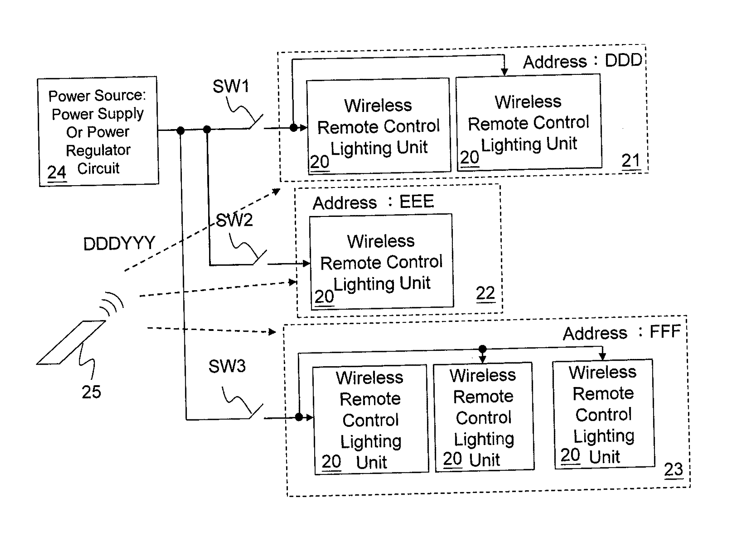
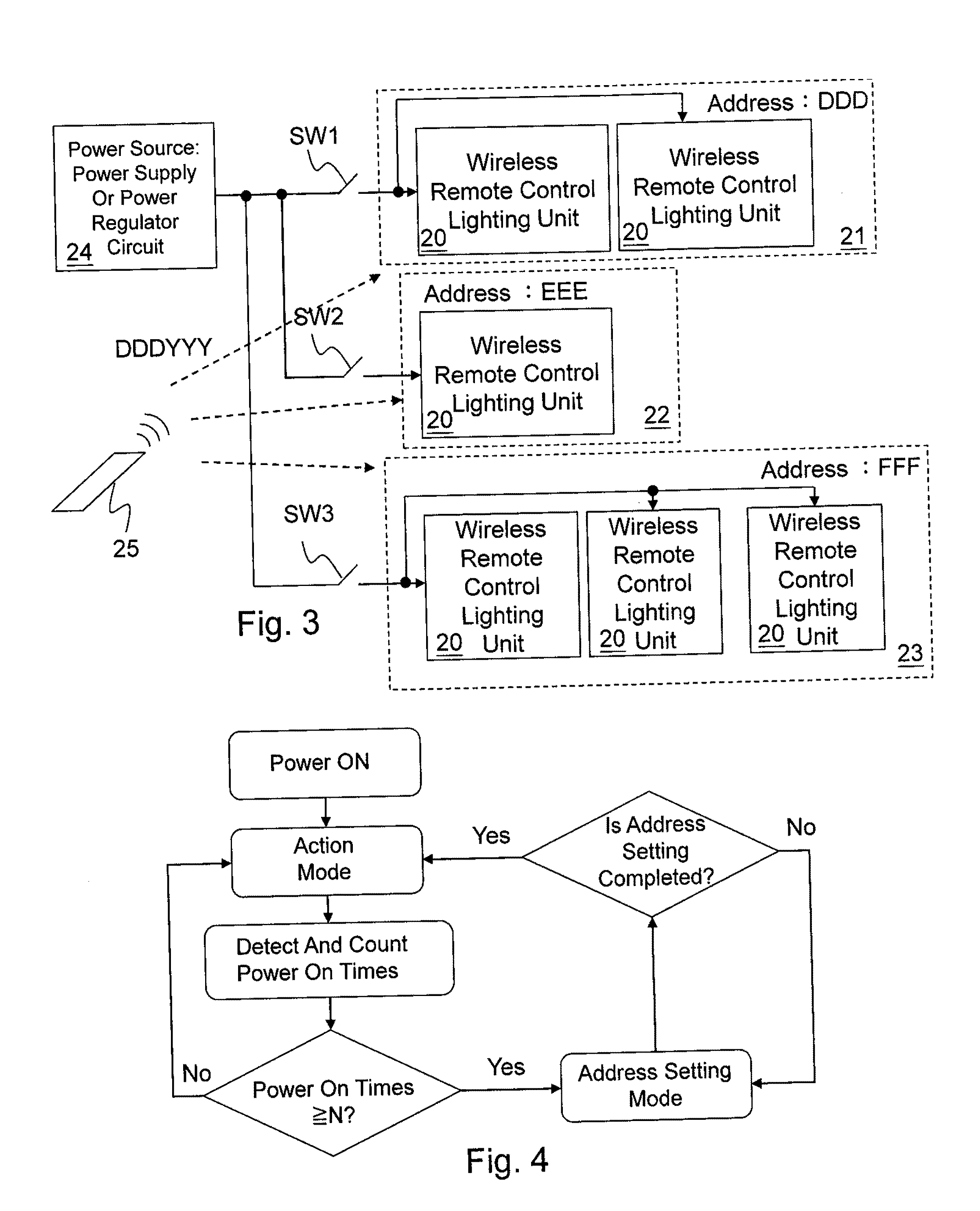
[0031]FIG. 3 shows an arrangement of lighting units according to the present invention. Each of the lighting groups 21, 22, and 23 comprises at least one wireless remote control lighting unit 20. In this embodiment, all units of the same lighting group are coupled to the same switch; as shown in the figure, the lighting groups 21, 22, and 23 are respectively connected to switches SW1, SW2, and SW3. (However, as a variation, it can certainly be arranged in a way that each lighting unit 20 is individually connected to its own switch.) Every wireless remote control lighting unit 20 belonging to the same lighting group may have an identical address; e.g., the address of each lighting unit 20 of the lighting group 21 is DDD, the address of each lighting unit 20 of the lighting group 22 is EEE, and the address of each lighting unit 20 of the lighting group 23 is FFF. The remote controller 25 transmits remote signals to each of wireless remote control lighting unit 20 through, for example ...


PUM


Abstract

The present invention discloses a wireless remote control lighting unit and a wireless remote control lighting system and a control method thereof. The wireless remote control lighting unit comprises a power on detection circuit, which detects and counts the power on times of a power source during a predetermined period. When the power on times reach a threshold number, the wireless remote control lighting unit enters an address setting mode to set its address.

Description

CROSS-REFERENCE[0001]The present invention claims priority to U.S. provisional application No. 61 / 322,440, filed on Apr. 9, 2010.BACKGROUND OF THE INVENTION[0002]1. Field of Invention[0003]The present invention relates to a wireless remote control lighting unit, a wireless remote control lighting system and a control method thereof, in particular to such wireless remote control lighting unit, wireless remote control lighting system and control method that do not require a complicated handshaking process for addressing.[0004]2. Description of Related Art[0005]FIG. 1 explains the operation for wireless control of lighting units. Lighting units 10A, 10B, and 10C have different addresses; for example, the address of the lighting unit 10A is AAA, that of the lighting unit 10B is BBB, and that of the lighting unit 10C is CCC. Through radio frequency (RF), infrared (IR), or other carriers, signals containing addresses, instructions and so on are transmitted and received between a remote co...

Claims


Application Information

Patent Timeline
IPC IPC(8): H05B37/02H02J13/00
CPCH05B37/0272H05B47/19
Inventor LIU, JING-MENGTU, SHEN
Owner RICHTEK TECH
Why Eureka
Try Eureka