Breathing apparatus

a breathing apparatus and positive airway technology, applied in the field of breathing apparatus, can solve the problems of reducing the pressure of the air supplied, increasing the pressure at the user's upper airway, and uncomfortable for the user,

Inactive Publication Date: 2011-10-20
INSLEEP TECH
View PDF21 Cites 62 Cited by
  • Summary
  • Abstract
  • Description
  • Claims
  • Application Information

AI Technical Summary

Problems solved by technology

However, when air is provided to the user's upper airways at a constant supply pressure, normal respiration of the user may result in decreases and increases in pressure at the user's upper airways.
The pressure variations caused by normal respiration, particularly increases in pressure resulting from exhalation by the user, are often found to be uncomfortable to the user.
Specifically, such systems may reduce the pressure of the air supplied to the user during exhalation of by the user.
Similarly, the systems may increase the pressure of the air supplied to the user during inhalation by the user.
However, the stochastic nature of breathing, may result in substantial control system complications.
Additionally, due to the pressure drop through an exhaust tube (e.g., which may exhaust the user's exhaled breath), a user may still experience uncomfortable resistance during exhalation.
While the relatively large diameter tube may generally reduce the exhalation resistance experienced by the user, increasing the diameter of the tube may generally increase the stiffness of the tube making the system less comfortable for the user and increasing the likelihood that user movement will displace the user interface, thereby diminishing the benefits of the positive airway pressure system.

Method used


Image

  • Breathing apparatus
  • Breathing apparatus
  • Breathing apparatus

Examples


Embodiment Construction

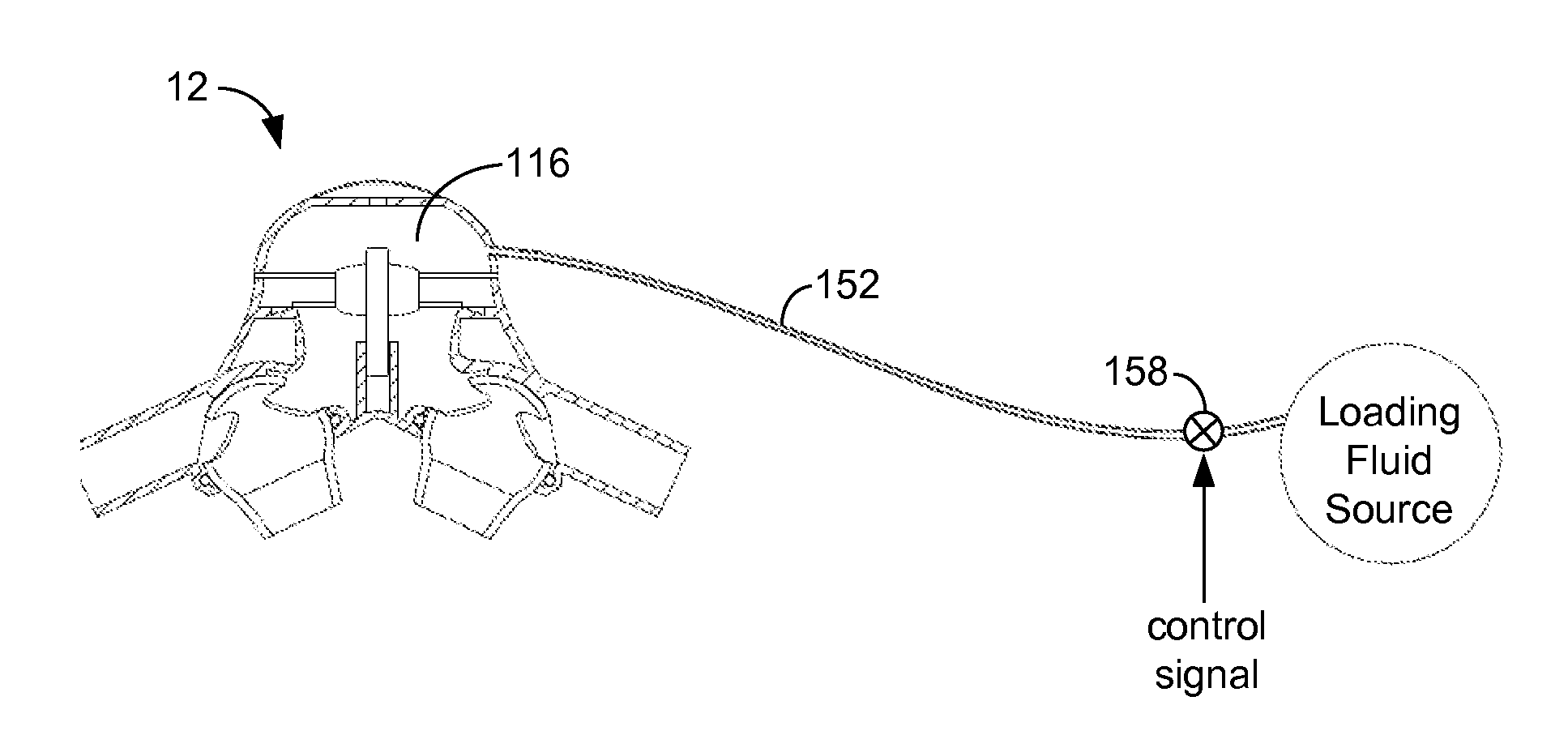
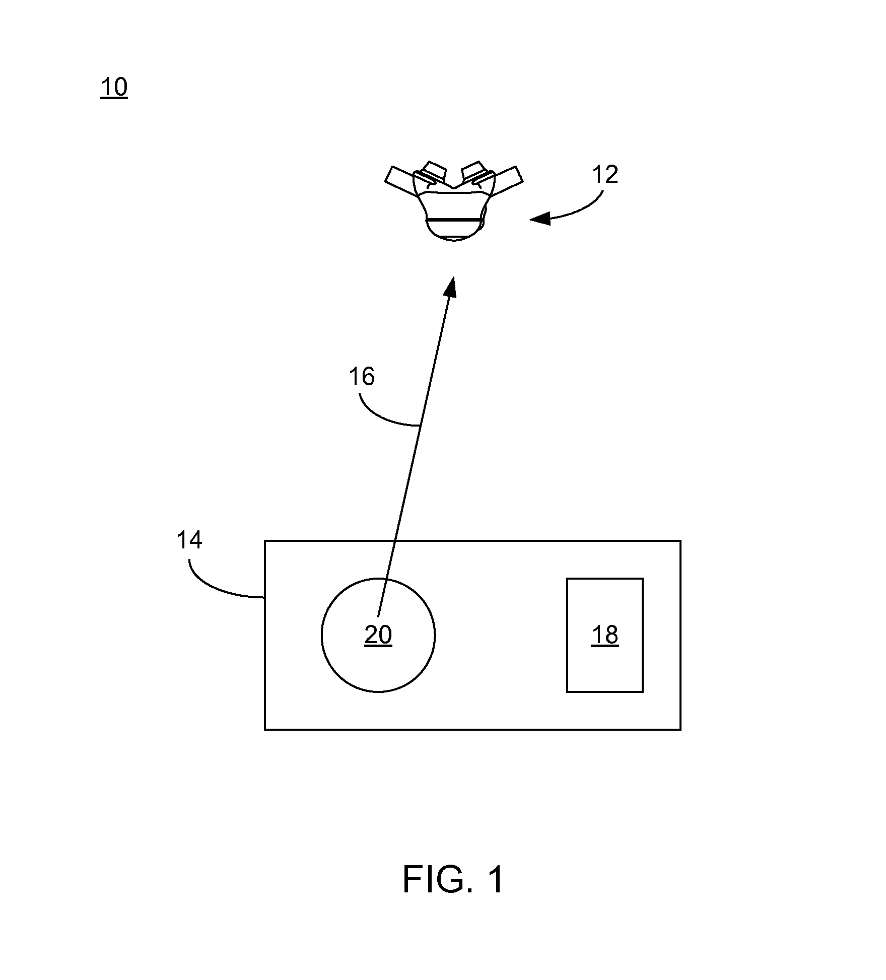
[0034]Referring to FIG. 1, breathing system 10 is generally shown including breathing apparatus 12 in conjunction with positive airway pressure (PAP) air supply 14. PAP air supply 14 may generally supply pressurized air (i.e., air at a pressure greater than ambient pressure, e.g., a pressure of 10 cm H2O above ambient pressure, although other pressures may be equally utilized, depending upon design criteria and user need). The pressurized air generated by PAP air supply 14 may be delivered to breathing apparatus 12 via supply tube 16. In an embodiment, supply tube 16 may include a relatively small diameter (e.g., 9.5 mm inside diameter tubing) which may allow relatively un-encumbered movement of breathing apparatus 12 relative to PAP air supply 14. While a 9.5 mm inside diameter supply tube has been described above, this should not be construed as a limitation of the present disclosure as other tubing sizes may be equally utilized depending upon design criteria and user need.

[0035]A...


PUM


Abstract

A breathing apparatus includes a supply tube configured to provide a supply of air. A first and second nasal interface each include a generally spherical member having a respective projection configured to be at least partially received within a respective nasal passage of a user, and are independently movable relative to the housing. A valve is disposed between the fluid chamber and an exhaust passage for selectively allowing air to be exhausted from the fluid chamber via the exhaust passage. A diaphragm, coupled to a bias chamber, is also coupled to the valve for moving the valve between the open position and the closed position. Bias pressure within the bias chamber is regulated, at least in part, by a loading fluid impedance and a venting fluid impedance.

Description

TECHNICAL FIELD[0001]The present disclosure generally relates to a breathing apparatus, and more particularly relates to a positive airway pressure-type breathing apparatus.BACKGROUND[0002]Various products have been developed for the treatment of snoring and of sleep apnea. One common approach is directed at maintaining positive airway pressure of a user in an attempt to prevent the closing of the user's airways. One general variety of positive airway pressure devices is the continuous positive airway pressure (CPAP) system, which seeks to maintain a constant pressure in the user's upper airways. However, when air is provided to the user's upper airways at a constant supply pressure, normal respiration of the user may result in decreases and increases in pressure at the user's upper airways. The pressure variations caused by normal respiration, particularly increases in pressure resulting from exhalation by the user, are often found to be uncomfortable to the user.[0003]Attempts to ...

Claims


Application Information

Patent Timeline
Patent Type & Authority Applications(United States)
IPC IPC(8): A61M16/00
CPCA61M16/06A61M16/0666A61M16/20A61M2205/42A61M16/206A61M16/0825A61M16/0069A61M16/201A61M16/205A61M2210/0618
Inventor GUSKY, MICHAEL H.EMAUS, JUDITHGAYLORD, DOUGLASHARRINGTON, STEVEN M.
Owner INSLEEP TECH
Why Eureka
Try Eureka