Intranasal Cartridge Devices

a cartridge device and cartridge technology, applied in the field of intranasal cartridge devices, can solve the problems of no longer being sterile, no longer being able to administer the substance, and being prone to abus

Active Publication Date: 2008-07-24
MYSTIC PHARMA INC
View PDF101 Cites 75 Cited by
  • Summary
  • Abstract
  • Description
  • Claims
  • Application Information

AI Technical Summary

Benefits of technology

[0025]In certain embodiments the mechanical advantage of the actuator can be provided by a pivoting linkage. A device with a pivot mechanism can include a pivot arm and a grip arm designed so a user holds the device in one hand with the fingers on the pivot arm and the thumb on the grip arm. The device is fired by squeezing the fingers and thumb together to bring the pivot arm into contact with the grip arm, or the progress of the pivot arm toward the grip arm can be limited before it reaches the grip arm, by the length of the piston stroke. The pivot arm includes an attachment to the body at a pivot point and a projection that enters the body of the device, forming a pivot ram that contacts the plunger or piston body. The pivot ram is closer to the pivot point than to the opposite end of the pivot arm. This placement of the pivot ram provides the mechanical advantage to the pivot mechanism.
[0026]An aspect of the design of a pivot arm device is the placement of the device during use. In order to deliver the full dosage amount to a user when the device is for intranasal delivery, it is important that the pharmaceutical is delivered and absorbed to the nasal mucosa rather than entering the throat or lungs of the user. The pivot device is designed to provide the correct alignment. When the device is held in the hand of a user as described and the discharge nozzle is placed into a nostril of the user, placing the thumb in the depression in the chin under the lower lip provides for the correct alignment. This method of holding the device also provides stability so the device can be held steady when the user fires it.
[0027]In certain embodiments, the mechanical advantage can be provided by a lever mechanism. In preferred embodiments the lever mechanism includes a lever arm in which the linkage is connected to the lever arm by a slidable hinge and pin connection. In this embodiment, a pin near the end of the linkage member or actuator slides in a groove or slot in a hinge attached to the lever arm. In the storage position, the lever arm is folded against the body, and as the arm is raised to the ready position the linkage slides in the slot until the end of the mechanism comes to rest in a notch in the underside of the lever arm. Placement of the end of the linkage in the notch prevents the linkage from sliding back along the lever arm and provides a steady base from which to force the linkage against the plunger. The mechanical advantage is provided by the placement of the notch nearer the attachment point of the lever arm to the body tha

Problems solved by technology

Another issue that arises with intranasal drug delivery devices is the potential for abuse.
In addition, if the unit dosage form is damaged, or is otherwise defective, the devices do not administer the substance, which may no longer be sterile.
For example, if an unit dosage form is defective in the area of the pierceable section, or develops a leak, the devices will not dispense the substance properly because sufficient pressure will not be generated in the unit dosage form to effectively release the substance.
The smaller size required by certain dosage situations, such as intranasal administration present greater challenges to the seal of the lid material to the blister material.
Mechanical disadvantage, as used

Method used


Image

  • Intranasal Cartridge Devices
  • Intranasal Cartridge Devices
  • Intranasal Cartridge Devices

Examples


Embodiment Construction

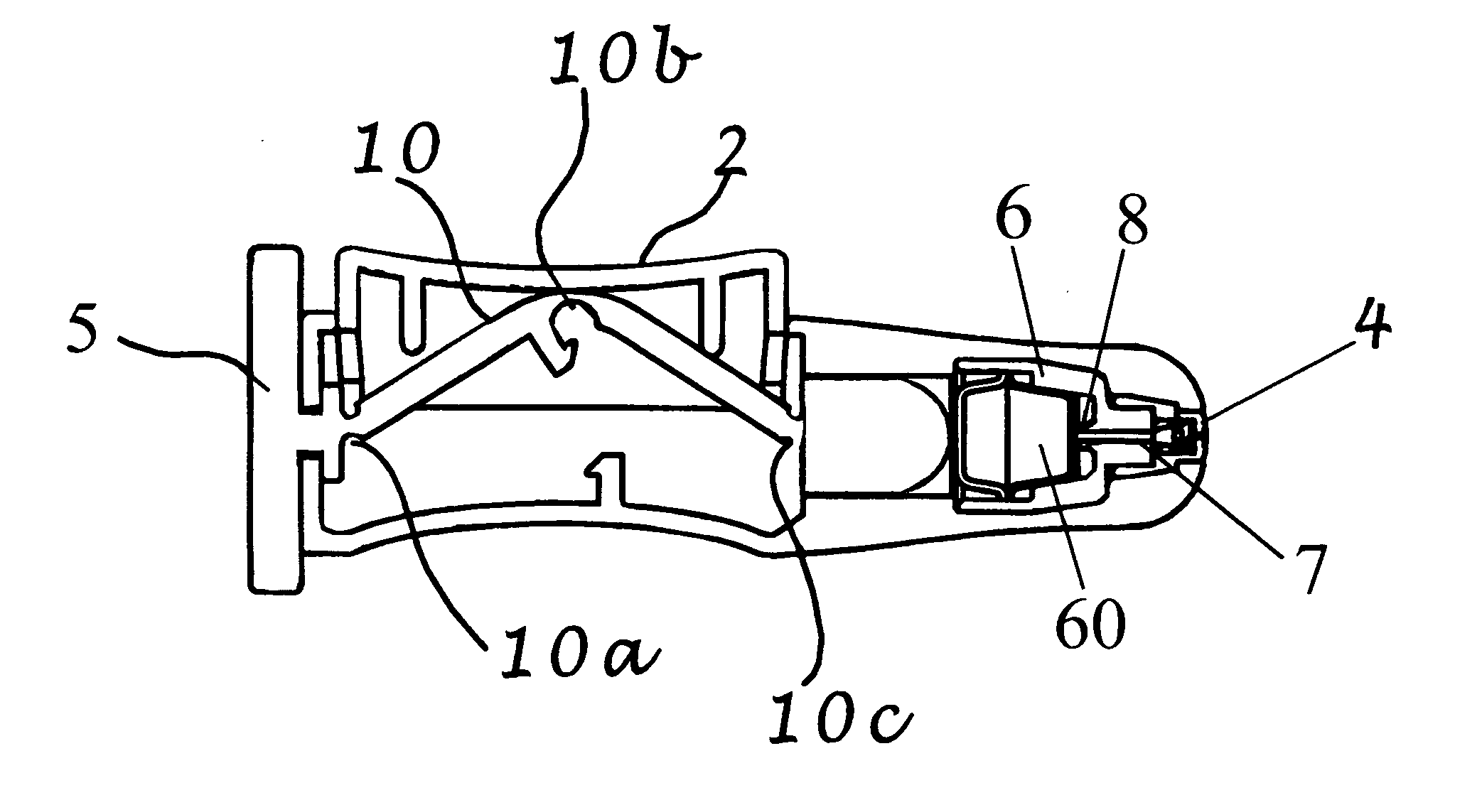
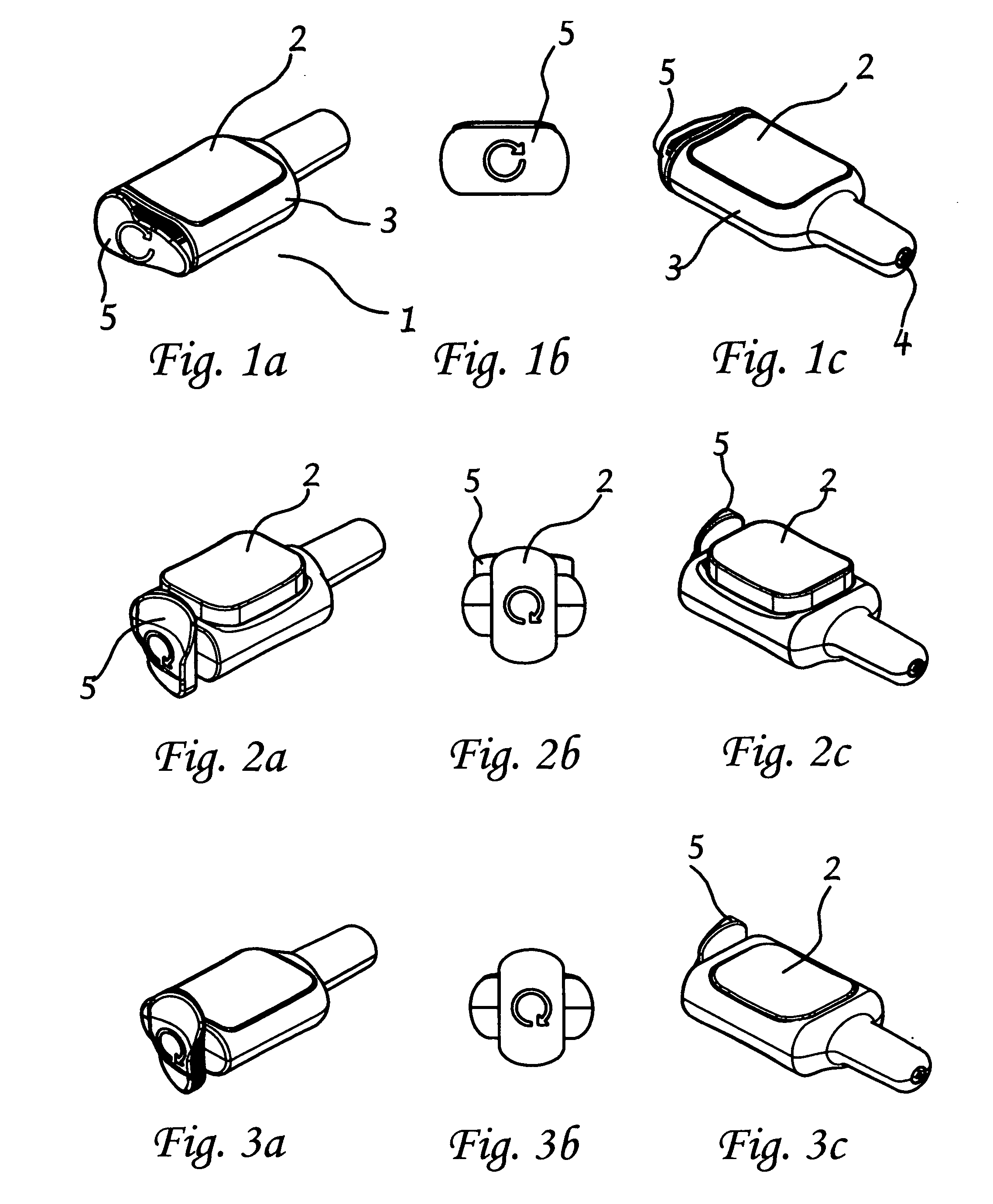
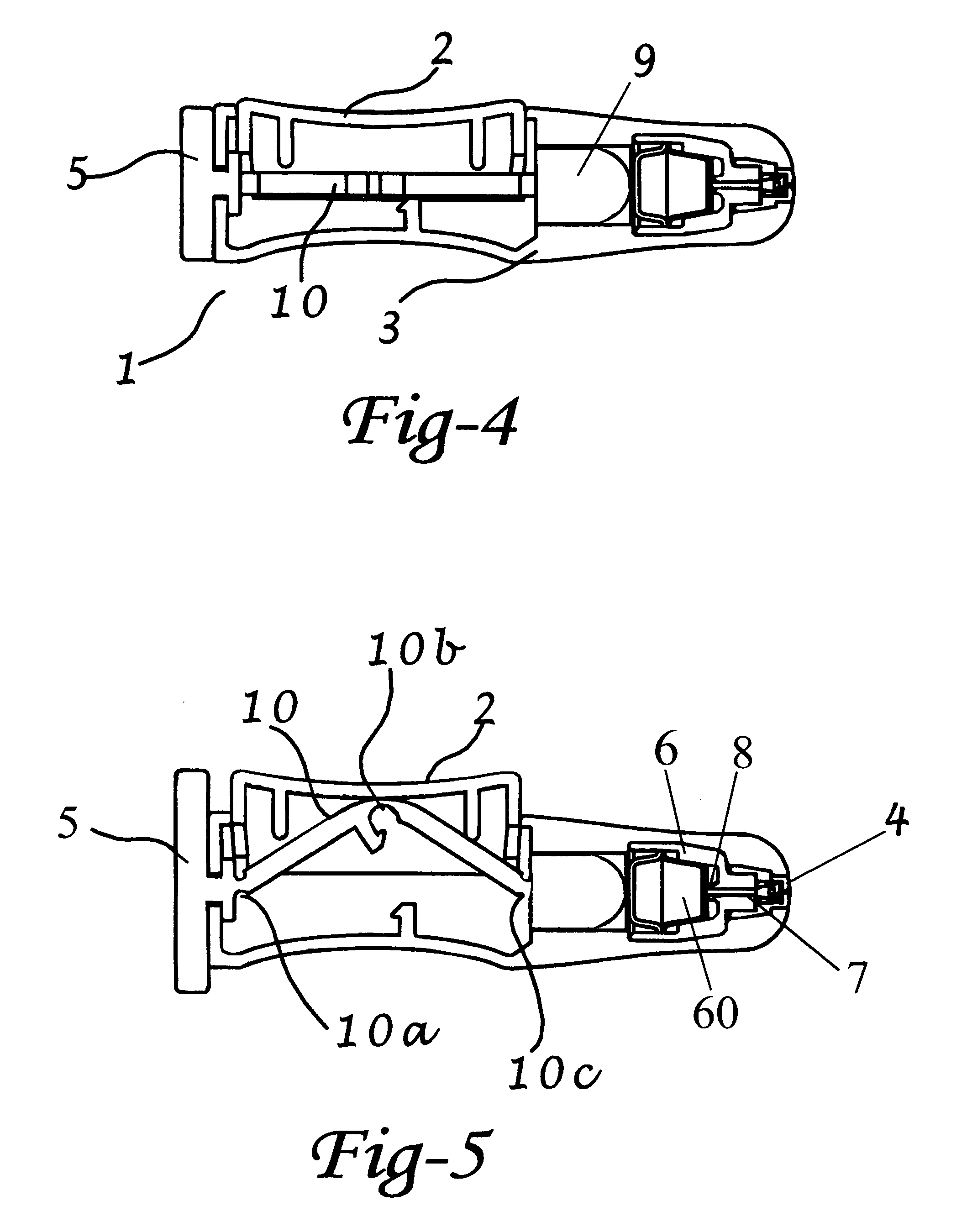
[0111]A preferred embodiment of an intranasal delivery device is shown in storage, ready and fired configurations in FIGS. 1, 2, and 3, respectively. The device 1 as shown, is a push button version of an intranasal delivery device. This embodiment includes a button 2, a body 3 with nozzle end 32 and an activation knob 5. The device shown in FIG. 1 is in storage mode, as can be seen by the positions of the activation knob 5, which is aligned with the body 3, and the button 2, which is in the depressed position. As shown, the activation knob 5, and the body 3, have a generally ovoid cross sectional shape. As used herein, when the activation knob 5 is in the storage position, the long axis of the activation knob 5 is aligned with the long axis of the body 3 cross section. A cross section of the push button device in storage position is shown in FIG. 4. In this view, the linkage 10 is horizontal under the button 2. The plunger 9 is in the retracted mode.

[0112]The embodiment of an intran...


PUM


Abstract

Intranasal delivery devices include dosage forms containing medical compositions for use in the intranasal devices, and methods of delivering medical compositions to the nasal mucosa of users. The devices dispense a predetermined quantity of fluid into the nasal passage of a user, in which the predetermined quantity of fluid is contained in, or produced in a dosage form or blister that is crushed by a plunger with sufficient force to drive the dosage form against a piercing mechanism, piercing the dosage form and forcing the liquid contents from the dosage form and through a delivery channel into a spray to be directed into the nasal passage of a user. The plunger is connected to a trigger device by a linkage that confers a mechanical advantage to the trigger mechanism.

Description

CROSS-REFERENCE TO RELATED APPLICATIONS[0001]This application claims benefit of priority of U.S. Provisional Application Ser. No. 60 / 853,328, filed Jan. 9, 2007, U.S. Provisional Application Ser. No. 60 / 944,700, filed Jun. 18, 2007, and U.S. Provisional Application Ser. No. 60 / 982,643, filed Oct. 25, 2007, the disclosures of which are all incorporated into this application in their entirety by reference for all purposes. In addition, the disclosures of commonly owned U.S. Provisional Applications Ser. Nos. 60 / 938,379, filed May 16, 2007 and 60 / 978,619, filed Oct. 9, 2007 are also incorporated into this application in their entirety by reference for all purposes.STATEMENT REGARDING FEDERALLY SPONSORED RESEARCH OR DEVELOPMENT[0002]N / ABACKGROUND OF THE INVENTION[0003]There is a growing number of drugs and vaccines for which the most effective, or most convenient method of administration is by intranasal delivery. This has led to the development of dosing devices for spray into the nose...

Claims


Application Information

Patent Timeline
IPC IPC(8): A61M5/28A61M5/42
CPCA61M5/2425A61M15/0051A61M15/06A61M15/08A61M2202/0468A61M2202/064A61M2205/073A61M2205/273A61M2205/583A61M2205/584A61M2205/6081A61M2206/16B05B11/0035B05B11/0081B05B11/0083B05B11/02B05B11/048B05B11/062B05B11/3056B05B11/3057A61M5/30A61M15/0028A61M2205/276A61M11/007A61M15/0003A61M15/0031A61M15/0036A61M15/004A61M11/06A61M11/002A61M15/0061B05B11/1056B05B11/1057
Inventor SULLIVAN, TIMOTHY R.NELSON, JEFFREYBRANDENBURG, ALLEN
Owner MYSTIC PHARMA INC
Why Eureka
Try Eureka