Motorized equipment

a motor and equipment technology, applied in the direction of magnetic circuit rotating parts, magnetic circuit shape/form/construction, transportation and packaging, etc., can solve the problems of increasing the manufacturing cost of the motor, increasing the body size in a radial direction, increasing etc., to and reduce the axial body size of the motorized equipment

Active Publication Date: 2011-10-20
DENSO CORP
View PDF10 Cites 55 Cited by
  • Summary
  • Abstract
  • Description
  • Claims
  • Application Information

AI Technical Summary

Benefits of technology

[0015]It is an object of the present invention to provide a motorized equipment enabling a design of a controller to be commonly used for electric motors having different output settings. It is another object of the present invention to provide a motorized equipment having a reduced body size.

Problems solved by technology

In this way, if the designs of the members constituting the controller and the like are changed according to the setting of the output of the electric motor, there is a concern that a manufacturing cost of the motor increases.
Since the motor described in Patent document 1 has the controller arranged parallel to the axial direction of the shaft of the electric motor, there is a concern that a body size in a radial direction increases.
Therefore, there is a concern that an axial body size increases.

Method used


Image

  • Motorized equipment
  • Motorized equipment
  • Motorized equipment

Examples


first embodiment

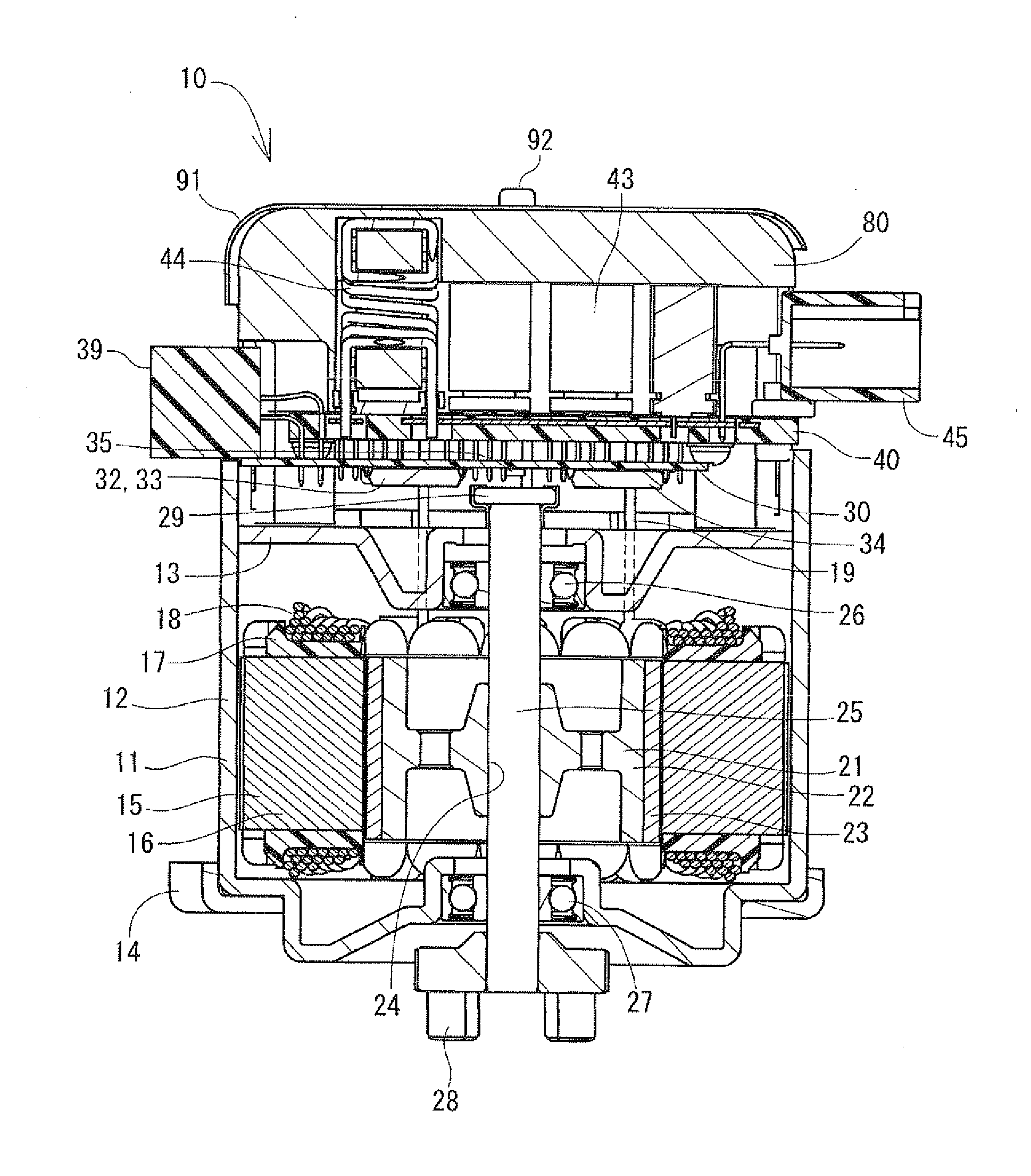
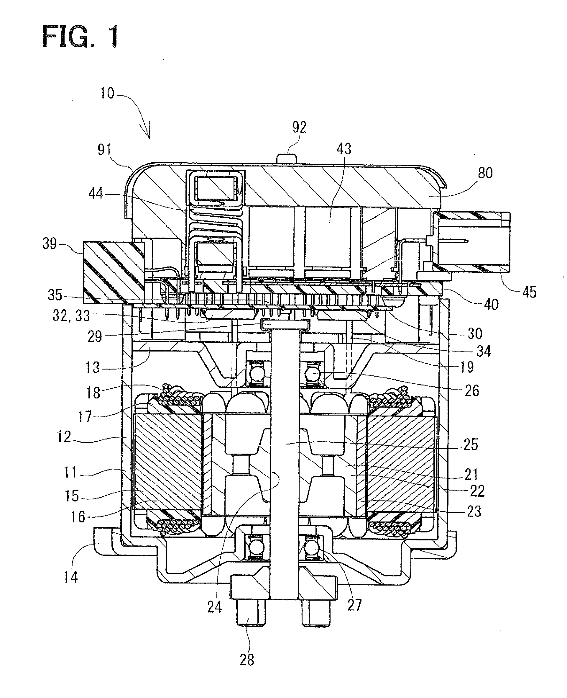
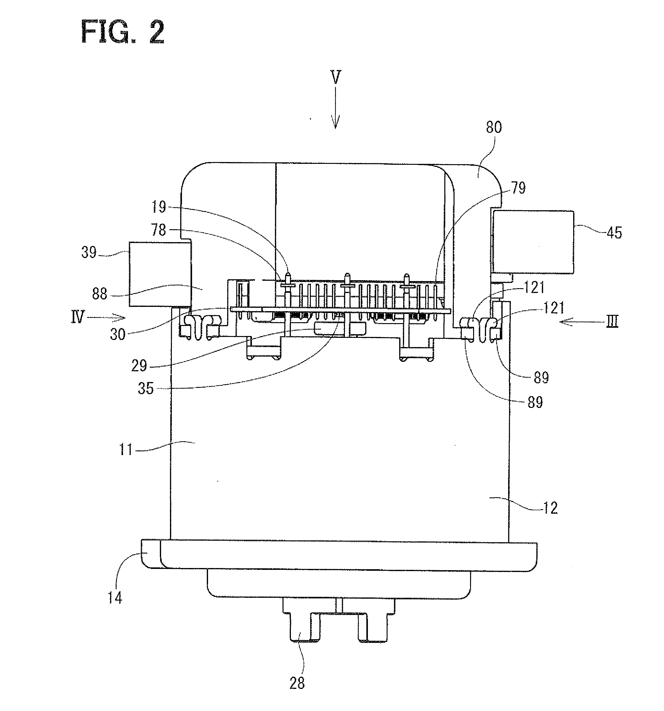
[0052]FIGS. 1 to 19 are diagrams each showing a motorized equipment according to a first embodiment of the present invention. The motorized equipment 10 according to the present embodiment is a brushless motor used for electric power steering. As shown in FIG. 6, the motorized equipment 10 meshes with a gear 2 of a column shaft 1. The motorized equipment 10 performs normal rotation and reverse rotation based on a vehicle speed signal, which is transmitted from CAN and the like, and a torque signal outputted from a torque sensor 4, which senses steering torque of a steering 3. Thus, the motorized equipment 10 generates a force for assisting steering.

[0053]FIG. 1 is a cross-sectional view showing the motorized equipment 10 according to the present embodiment. FIGS. 2 to 5 are views each showing outer appearance of the motorized equipment 10 according to the present embodiment. FIG. 7 is an exploded perspective view showing the motorized equipment 10 according to the present embodiment...

second embodiment

[0086]Next, a second embodiment of the present invention will be described. A motorized equipment 10 according to the present embodiment is shown in FIGS. 20 and 21. The motorized equipment 10 according to the present embodiment has a shield member 93 between the position sensor 35 and the power module 40. The shield member 93 is made of a material such as iron having high magnetic permeability.

[0087]A large current supplied from the battery 5 flows through the wirings 70-75 of the power module 40 as shown by an arrow mark A in FIG. 21. Therefore, an electromagnetic field is generated as shown by arrow marks B. If the electromagnetic field acts on the position sensor 35, there is a possibility that an error arises in the signal outputted from the position sensor 35.

[0088]Regarding this point, in the present embodiment, the electromagnetic field generated by the large current flowing through the wirings 70-75 of the power module 40 flows along the shield member 93. Therefore, the pos...

third embodiment

[0089]Next, a third embodiment of the present invention will be described. FIG. 22 shows a motorized equipment according to the present embodiment. In the present embodiment, a shield member 94 is formed in the shape of a flat plate. Thus, the control board 30 can be shielded over a wide area and a processing cost of the shield member 94 can be reduced.


PUM


Abstract

A power module, a control board and a heat sink are provided on one axial side of a shaft of an electric motor, which consists of a motor case, a stator, a rotor, the shaft and the like. The power module is electrically connected with extraction lines, which extend from a coil wound around the stator, and supplies a drive current to the coil. The control board for controlling switching of the power module is provided on a motor case side of the power module. The heat sink is provided on a side of the control board opposite to the motor case. Thus, when setting of an output of the electric motor is changed, a body size of the heat sink can be changed without changing a positional relationship between the control board and the electric motor and a positional relationship between the power module and the electric motor.

Description

CROSS REFERENCE TO RELATED APPLICATION[0001]This application is based on and incorporates herein by reference Japanese Patent Application No. 2010-94788 filed on Apr. 16, 2010.BACKGROUND OF THE INVENTION[0002]1. Field of the Invention[0003]The present invention relates to a motorized equipment having a controller provided on one axial side of a shaft of an electric motor.[0004]2. Description of Related Art[0005]Conventionally, electric power steering for assisting steering, which is performed by a driver, has been publicly known. Reduction of a size and weight and enhancement of an output of a motor used for the electric power steering are required.[0006]A motor described in Patent document 1 (JP-A-2003-204654) has a controller, which drives and controls an electric motor, provided parallel to an axial direction of a shaft of the electric motor. The electric motor is composed of a motor case, a stator, a rotor, the shaft and the like (refer to FIGS. 14 and 15 of Patent document 1). ...

Claims


Application Information

Patent Timeline
Patent Type & Authority Applications(United States)
IPC IPC(8): H02K5/22H02K1/04
CPCB62D5/0406H02K9/22H02K11/0073H02K11/33H02K9/227
Inventor YAMASAKI, MASASHI
Owner DENSO CORP
Why Eureka
Try Eureka