Apparatus, method and computer program for upmixing a downmix audio signal using a phase value smoothing

audio signal technology, applied in the field of apparatus, a computer program and a phase value smoothing technology, can solve the problems of degraded audio quality of binaural cue coding decoders, poor audio quality, etc., and achieve the effect of improving the hearing impression, small settling time, and sufficiently good smoothing characteristics

Active Publication Date: 2011-10-20
FRAUNHOFER GESELLSCHAFT ZUR FOERDERUNG DER ANGEWANDTEN FORSCHUNG EV
View PDF5 Cites 51 Cited by
  • Summary
  • Abstract
  • Description
  • Claims
  • Application Information

AI Technical Summary

Benefits of technology

[0024]This embodiment according to the invention is based on the finding that audible artifacts in the upmix signals can be reduced or even avoided by combining a scaled version of a previous smoothened phase value with a scaled version of an input phase information using a phase change limitation algorithm, because the consideration of the previous smoothened phase value in combination with a phase change limitation algorithm allows to keep discontinuities of the smoothened phase values reasonably small. A reduction of discontinuities between subsequent smoothened phase values (for example, the previous smoothened phase value and the current smoothened phase value), in turn, helps to avoid (or keep sufficiently small) audible frequency variation at a transition between portions of an audio signal to which the subsequent phase values (e.g. the previous smoothened phase value and the current smoothened phase value) are applied.
[0025]To summarize the above, the invention creates a general concept of adaptive phase processing for parametric multi-channel audio coding. Embodiments according to the invention supersede other techniques by reducing artifacts in the output signal caused by coarse quantization or rapid changes of phase parameters.
[0026]In an embodiment, the parameter determinator is configured to combine the scaled version of the previous smoothened phase value with the scaled version of the input phase information, such that the current smoothened phase value is in a smaller angle region out of a first angle region and a second angle region, wherein the first angle region extends, in a mathematically positive direction, from a first start direction defined by the previous smoothened phase value to a first end direction defined by the phase input information, and wherein the second angle region extends, in the mathematically positive direction, from a second start direction defined by the input phase information to a second end direction defined by the previous smoothened phase value. Accordingly, in some embodiments of the invention, a phase variation, which is introduced by a recursive (infinite impulse response type) smoothening of phase values, is kept as small as possible. Accordingly, audible artifacts are kept as small as possible. For example, the apparatus may be configured to ensure that the current smoothened phase value is located within a smaller angle range out of two angle ranges, wherein a first of the two angle ranges covers more than 180° and wherein a second of the angle ranges covers the less than 180°, and wherein the two angle ranges together cover 360°. Accordingly, it is ensured by the phase change limitation algorithm that the phase difference between the previous smoothened phase value and the current smoothened phase value is smaller than 180° and even smaller than 90°. This helps to keep audible artifacts as small as possible.
[0032]In an embodiment, the parameter determinator is configured to adjust the filter time constant for determining a sequence of the smoothened phase values in dependence on a current difference between a smoothened phase value and a corresponding input phase value. By adjusting the filter time constant, it can achieved that a sufficiently small settling time is obtained for very large changes of the input phase value, while keeping the smoothing characteristics sufficiently good for lower and medium changes of the input phase value. This functionality brings along particular advantages, because a comparatively small (or, at most, medium-sized) change of the input phase value is often caused by a quantization granularity. In other words, a stepwise change of the input phase value, which is caused by a quantization granularity, may result in an efficient operation of the smoothing. In such a case, the smoothing functionality may be particularly advantageous, wherein a comparatively long filter time constant brings good results. In contrast, a very large change of the input phase value, which is significantly larger than a quantization step, typically corresponds to a desired large change of the phase value. In this case, a comparatively short filter time constant brings along good results. Accordingly, by adjusting the filter time constant in dependence on a current difference between a smoothened phase value and a corresponding input phase value, it can be reached that, intentional large changes of the input phase value result in fast changes of the smoothened phase values, while comparatively small changes of the input phase value, which take the size of a quantization step, result in a comparatively slow and smoothed transition of the smoothened phase value. Accordingly, a good hearing impression is reached both for intentional, large changes of the desired phase value and for small changes of the desired phase value (which, nevertheless, may cause a change of the input phase value by one quantization step).

Problems solved by technology

Some conventional interpolation approaches, however, result in poor audio quality.
However, it has been found that many conventional binaural cue coding decoders provide multi-channel output audio signals with degraded quality if the side information is quantized coarsely or with insufficient resolution.
Thus, a smoothing of the phase values, which improves the auditory impression in most cases, would be detrimental in this specific case.

Method used


Image

  • Apparatus, method and computer program for upmixing a downmix audio signal using a phase value smoothing
  • Apparatus, method and computer program for upmixing a downmix audio signal using a phase value smoothing
  • Apparatus, method and computer program for upmixing a downmix audio signal using a phase value smoothing

Examples


Embodiment Construction

1. EMBODIMENT ACCORDING TO FIG. 1

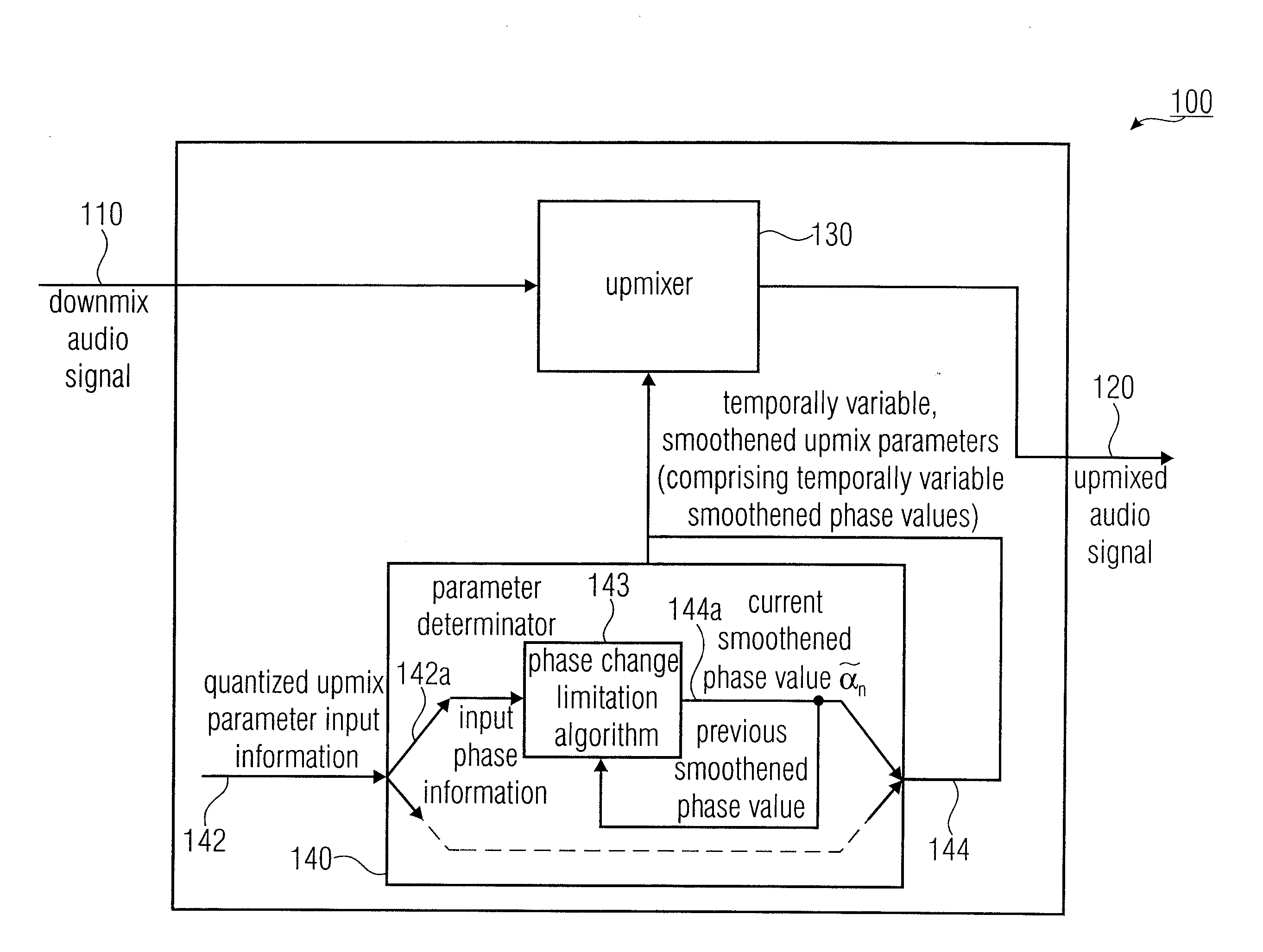
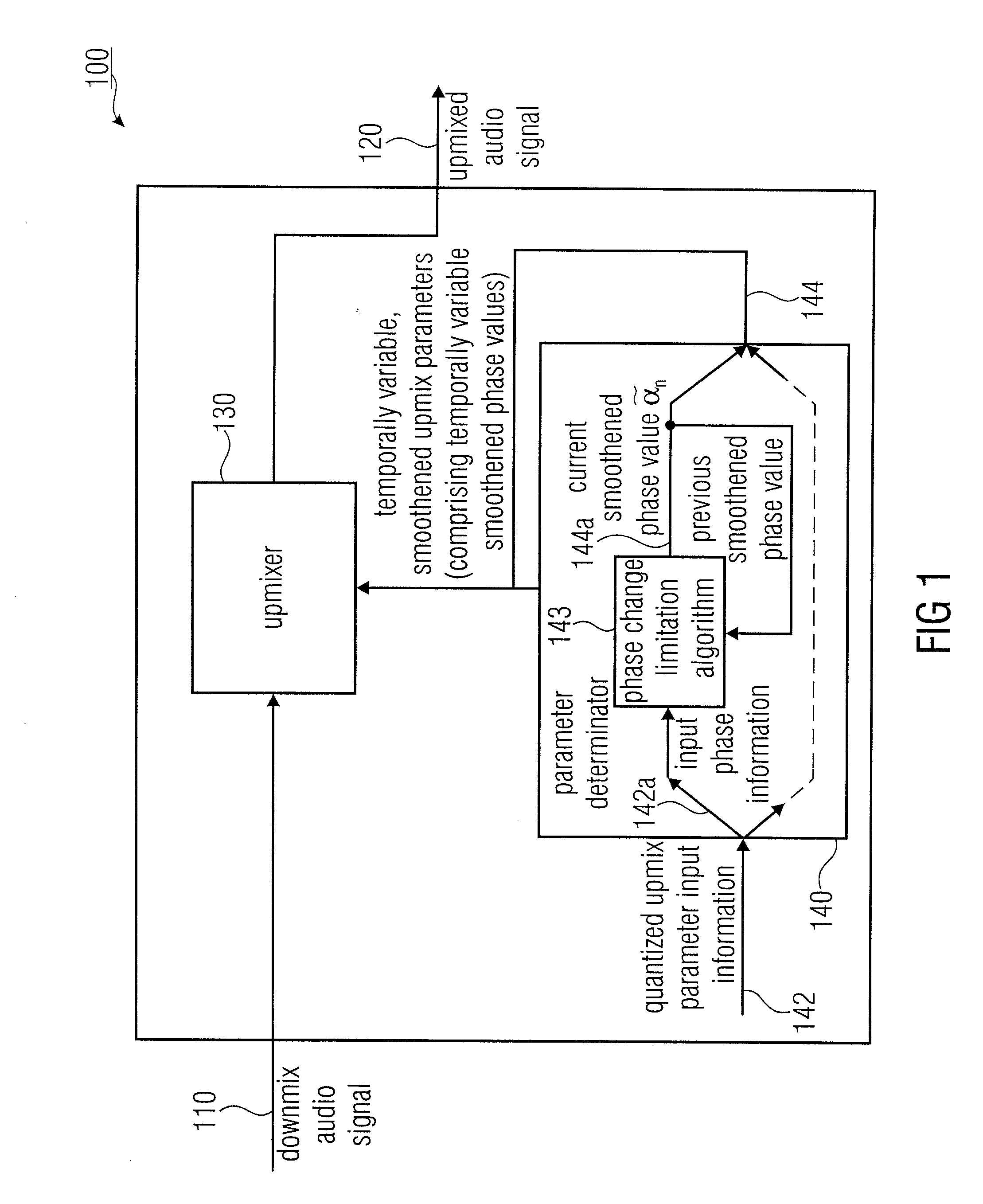
[0045]FIG. 1 shows a block schematic diagram of an apparatus 100 for upmixing a downmix audio signal, according to an embodiment of the invention. The apparatus 100 is configured to receive a downmix audio signal 110 describing one or more downmix audio channels and to provide an upmixed audio signal 120 describing a plurality of upmixed audio channels. The apparatus 100 comprises an upmixer 130 configured to apply temporally variable upmix parameters to upmix the downmix audio signal 110 in order to obtain the upmixed audio signal 120. The apparatus 100 also comprises a parameter determinator 140 configured to receive quantized upmix parameter input information 142. The parameter determinator 140 is configured to obtain one or more temporally smoothened upmix parameters 144 for usage by the upmixer 130 on the basis of the quantized upmix parameter input information 142.

[0046]The parameter determinator 140 is configured to combine a scaled version of...


PUM


Abstract

An apparatus for upmixing a downmix audio signal describing one or more downmix audio channels into an upmixed audio signal describing a plurality of upmixed audio channels includes an upmixer and a parameter determinator. The upmixer is configured to apply temporally variable upmix parameters to upmix the downmix audio signal in order to obtain the upmixed audio signal, wherein the temporally variable upmix parameters include temporally variable smoothened phase values. The parameter determinator is configured to obtain one or more temporally smoothened upmix parameters for usage by the upmixer on the basis of a quantized upmix parameter input information. The parameter determinator is configured to combine a scaled version of a previous smoothened phase value with a scaled version of an input phase information using a phase change limitation algorithm, to determine a current smoothened phase value on the basis of the previous smoothened phase value and the phase input information.

Description

CROSS-REFERENCE TO RELATED APPLICATIONS[0001]This application is a continuation of copending International Application No. PCT / EP2010 / 054448, filed Apr. 1, 2010, which is incorporated herein by reference in its entirety, and additionally claims priority from U.S. Application No. 61 / 167,607 filed Apr. 8, 2009, which is incorporated herein by reference in its entirety.BACKGROUND OF THE INVENTION[0002]Embodiments according to the invention are related to an apparatus, a method, and a computer program for upmixing a downmix audio signal.[0003]Some embodiments according to the invention are related to an adaptive phase parameter smoothing for parametric multi-channel audio coding.[0004]In the following, the context of the invention will be described. Recent development in the area of parametric audio coding delivers techniques for jointly coding a multi-channel audio (e.g. 5.1) signal into one (or more) downmix channels plus a side information stream. These techniques are known as Binaur...

Claims


Application Information

Patent Timeline
Patent Type & Authority Applications(United States)
IPC IPC(8): H04B1/00
CPCH04S2420/03G10L19/008H04S3/00
Inventor NEUSINGER, MATTHIASROBILLIARD, JULIENHILPERT, JOHANNES
Owner FRAUNHOFER GESELLSCHAFT ZUR FOERDERUNG DER ANGEWANDTEN FORSCHUNG EV
Why Eureka
Try Eureka