BigFoot Mobility Device End Tip

a technology for mobility devices and canes, applied in walking aids, crutches, physical therapy, etc., can solve the problems of quad bases being a real trip hazard, quad bases contributing little to improving user comfort, safety or convenience, etc., and achieves the effects of widening the diameter, enhancing the compressibility, and altering the dimensions and functionality of components

Inactive Publication Date: 2011-10-27
ADAMS MICHAEL
View PDF5 Cites 17 Cited by
  • Summary
  • Abstract
  • Description
  • Claims
  • Application Information

AI Technical Summary

Benefits of technology

[0009]The hexagonal base of the present invention is significantly wider in diameter as compared to the prior art, thus altering the dimensions and the functionality of the components of the end piece. The base is between about 100 and 130 millimeters in diameter; the “rib-like” frame lies at about a 40-50 degree angle above the horizontal plane; and in a preferred embodiment is about 45 degrees. The associated recessed panels are of about 37 to 41 millimeters in height; and the ribs of about 7 to 11 millimeters in thickness. This structural alteration provides enhanced levels of compressibility, otherwise known as shock absorption, and stability of the mobile device, while also providing a novel mechanism to affect forward propulsion of the user.
[0010]In a further embodiment of the present invention, the ribs framing the mobility device tip are of two different sizes to enhance shock absorption, stability, and the forward propulsion of the user. From an overhead, cross-sectional view of the tip for forward motion, the two ribs in the tip front 1100 and 100 (at 11 and 1 o'clock) and the two ribs in the tip rear 500 and 700 (at 5 and 7 o'clock) are thicker than the two ribs on the tip sides 300 and 900 (at 3 and 9 o'clock). The front and rear ribs are also slightly longer than the side ribs. Furthermore, the width of each rib may be uniform or not. All six ribs possess a wider end connecting with the bottom floor hexagonal base as compared to remainder of their rib length. The wider, terminal end of each rib at the floor engaging base improves stability, while the thinner mid-section of the ribs provides enhanced compressive and rebound forces and flexibility in the tip as a whole, while also providing a variably manifested “spring-like” force to assist in propelling the user forward.
[0011]In another aspect of the present invention, the bottom floor engaging base is hexagonal in shape, and concave in a downwardly facing surface direction, and with a plurality of alternating rubber rings and recesses. Additionally, the perimeter, and tallest protrusion ring is quickly angled vertically from its outer rim towards the tip center such that the only point-of-contact of the mobility device with the floor when the device is in a vertical, unloaded position is the outer rim of the perimeter ring. This is for the purpose of minimizing the traction force that must be overcome when lifting the mobility device off the floor, while optimizing the traction and compressive forces when the mobility device is supporting the user's weight. As either vertical or oblique compressive forces are applied to the mobility device by the user, the perimeter protrusion ring laterally expands and flattens downward such that the entire diameter of the ring ultimately comes in contact with the floor. The plurality of alternating rubber rings and recesses provide enhanced traction and compression by permitting the floor engaging rings (e.g. protrusion rings) to laterally expand and thus maximize contact with the floor when under compressive loads.

Problems solved by technology

While preferable to a blunt wood or metal shaft, these tips contribute little to improving user comfort, safety or convenience.
Improvements in overall support are marginal, however, and the combination of expensive materials and a sophisticated construction are reflected in its premium price.
For all these benefits, however, quad bases offer just intermittent support, and are typically comprised of several cumbersome and heavy steel parts.
Additionally, large gaps between the tubular legs, and the ease with which those legs can snag or catch on any number of surfaces, make quad bases a real trip hazard.
While this does make a device self-standing, the deep voids between the “tip arms” still present a trip hazard, and the north / south / east / west orientation of the contact points is even more problematic than a typical quad base in terms of abrupt, “on again-off again” support.
However, the effectiveness of the spring-biased lobe in response to loads is highly variable, and the large voids between the lobes provide no support to stabilize the user throughout their gait.
To date, however, no known device has been of sufficient size, configuration and construction to offer greatly enhanced support and stability, omnidirectional shock absorption and spring assist, an “unbroken” bottom rim, a self-standing feature, improved traction, and a low cost to manufacture all in a single product.

Method used


Image

  • BigFoot Mobility Device End Tip
  • BigFoot Mobility Device End Tip
  • BigFoot Mobility Device End Tip

Examples


Embodiment Construction

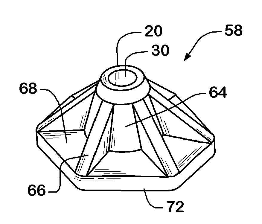
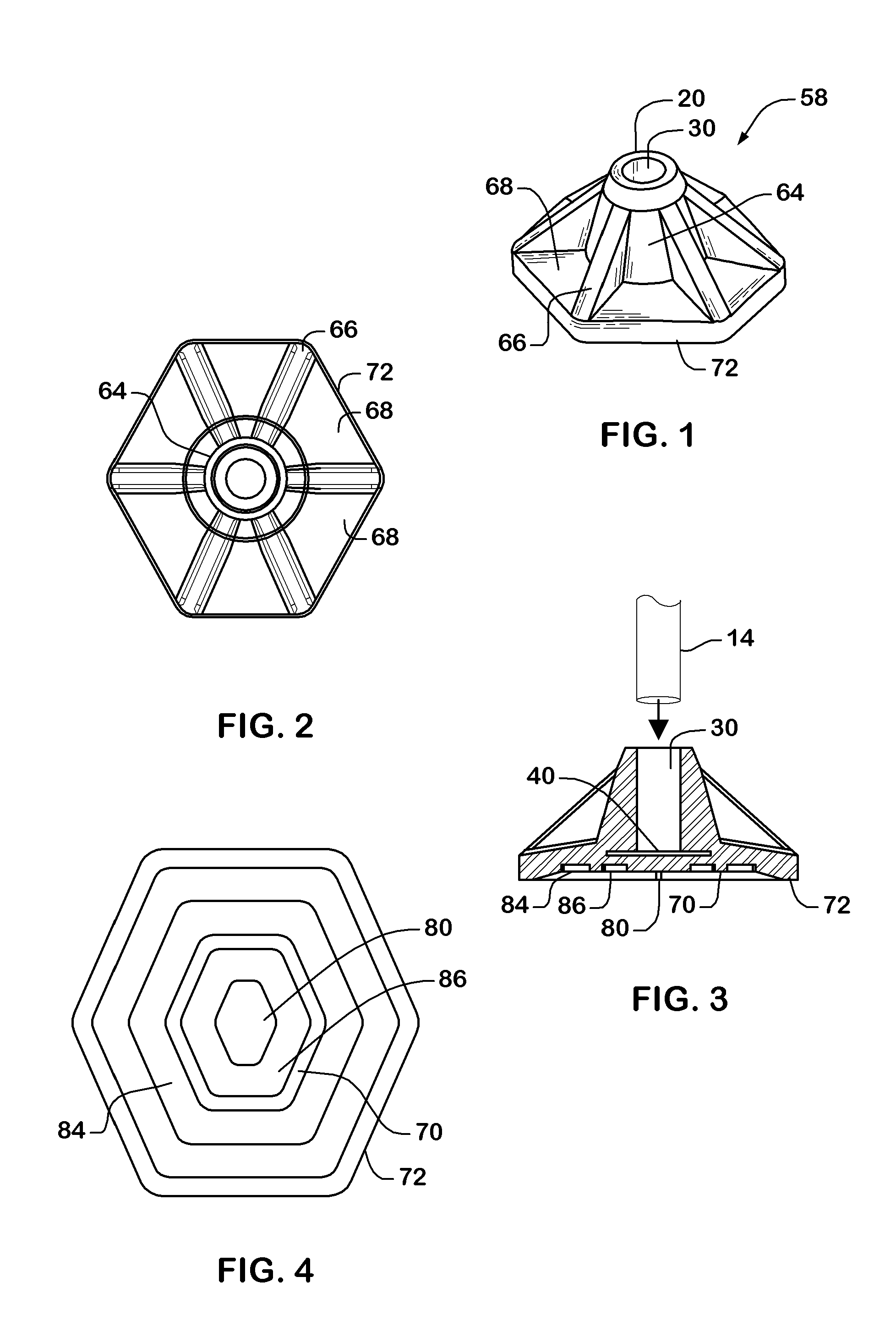
[0018]Previously, the prior art of the inventor of the present invention disclosed and claimed a mobility device comprising a hexagonal end tip as shown in U.S. Pat. No. 7,610,926 issued Nov. 3, 2009 entitled “Mobility Device”, the entirety of which is incorporated by reference. In particular, FIGS. 13-18 of U.S. Pat. No. 7,610,926 disclosed a pseudo-frustoconical shape with six facets or side walls 62. Each side wall 62 includes a depressed panel 64 surrounded by an outstanding rib-like frame 66, wherein the depressed panels are of a few millimeters in depth such that the side walls are almost vertical. The present invention is based on an unexpected discovery that a user of a mobility device experiences much increased stability, compressibility and measureable spring assistance to their ambulation when the end piece is re-modeled by dramatically increasing the depth of the depressed panels so as to make the resultant, circumferential ribs much more prominent. Additionally, a novel...


PUM


Abstract

A pseudo-frustoconical shaped unitary rubber end unit for an ambulatory device, such as a cane, comprising, a bottom hexagonal base and a top circular rim, wherein said base is about four times the diameter of said rim and functions to provide significantly enhanced support and stability; and a central cylindrical “socket” created by six deeply recessed side walls and a resultant six member rib-like frame that functions to optimize device's shock absorption capabilities and forward propulsion of the user. The hexagonal base may be asymmetrical or symmetrical, and the ribs may be of uniform or non-uniform dimensions. The hexagonal base and the rib-like frame act synergistically to compress and rebound under loads creating a twisting “spring assist” action that both absorbs shock and helps propel users forward. The broad base has a slightly recessed underside permitting the mobility device to be self-standing.

Description

PRIORITY CLAIMS TO RELATED PROVISIONAL APPLICATIONS[0001]The present application claims priority benefit to U.S. Provisional Patent Application Ser. No. 61 / 343,129, filed Apr. 23, 2010 by Michael E. Adams, entitled “6 sided substantially conical elastomeric broad base shock absorbing floor tip for canes and crutches”, the disclosure of which is incorporated by reference.TECHNICAL FIELD OF THE INVENTION[0002]This invention relates generally to tips and bases for canes and related ambulatory aids, and more specifically to those tips and bases having both sufficient size so as to markedly improve the support and stability of such devices, and an overall construction specifically designed to actively assist a user moving through a gait cycle.BACKGROUND OF THE INVENTION[0003]Tips or bases of different sizes and configurations have long been fitted to the bottom end of canes and other ambulatory aids. To a greater or lesser degree, each is designed to absorb shock, increase support and st...

Claims


Application Information

Patent Timeline
Patent Type & Authority Applications(United States)
IPC IPC(8): A45B9/04
CPCA45B9/04A61H3/0288
Inventor ADAMS, MICHAEL E
Owner ADAMS MICHAEL
Why Eureka
Try Eureka