Power-supplying device, control method for the same, and power-supplying system

a power supply device and control method technology, applied in the direction of secondary cell servicing/maintenance, electrochemical generators, safety/protection circuits, etc., can solve the problems of excessive power supply, less power efficiency of the primary coil and the secondary coil, and the assumption of power supply over conventional techniques

Active Publication Date: 2011-10-27
CANON KK
View PDF0 Cites 58 Cited by
  • Summary
  • Abstract
  • Description
  • Claims
  • Application Information

AI Technical Summary

Benefits of technology

[0004]The present invention has been made in consideration of the above problems in the prior art. The present invention provides a power-supplying device, which can properly supply power to each power-supplied dev

Problems solved by technology

By using this electromagnetic induction to supply power, the displacement between the primary coil and the secondary coil will become the less power efficiency or cause excessive power supply.
The a

Method used


Image

  • Power-supplying device, control method for the same, and power-supplying system
  • Power-supplying device, control method for the same, and power-supplying system
  • Power-supplying device, control method for the same, and power-supplying system

Examples


Embodiment Construction

[0015]An embodiment of the present invention will be described below with reference to the accompanying drawings. However, the embodiment of the present invention exemplifies a preferred embodiment of the present invention, and does not limit the scope of the invention.

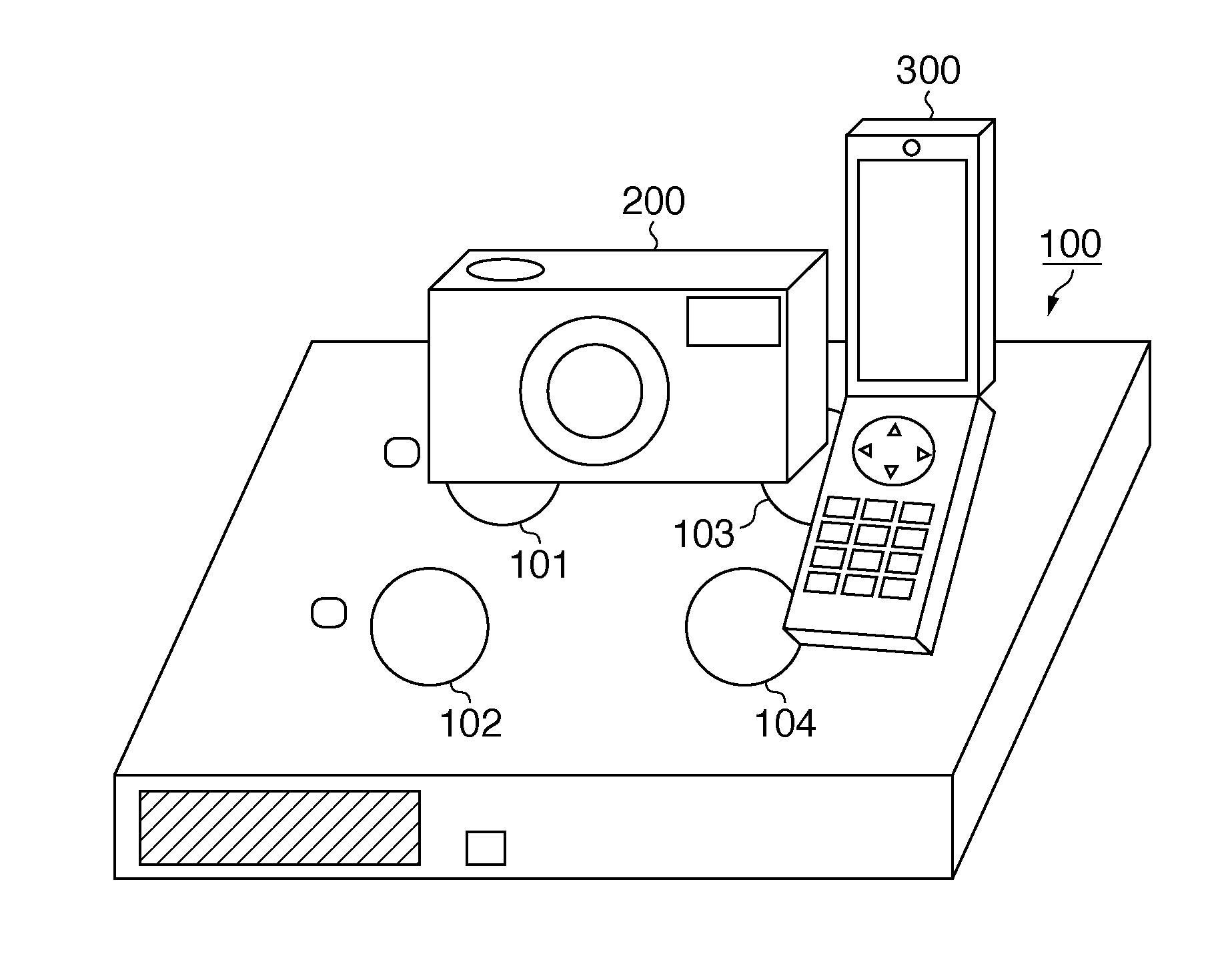
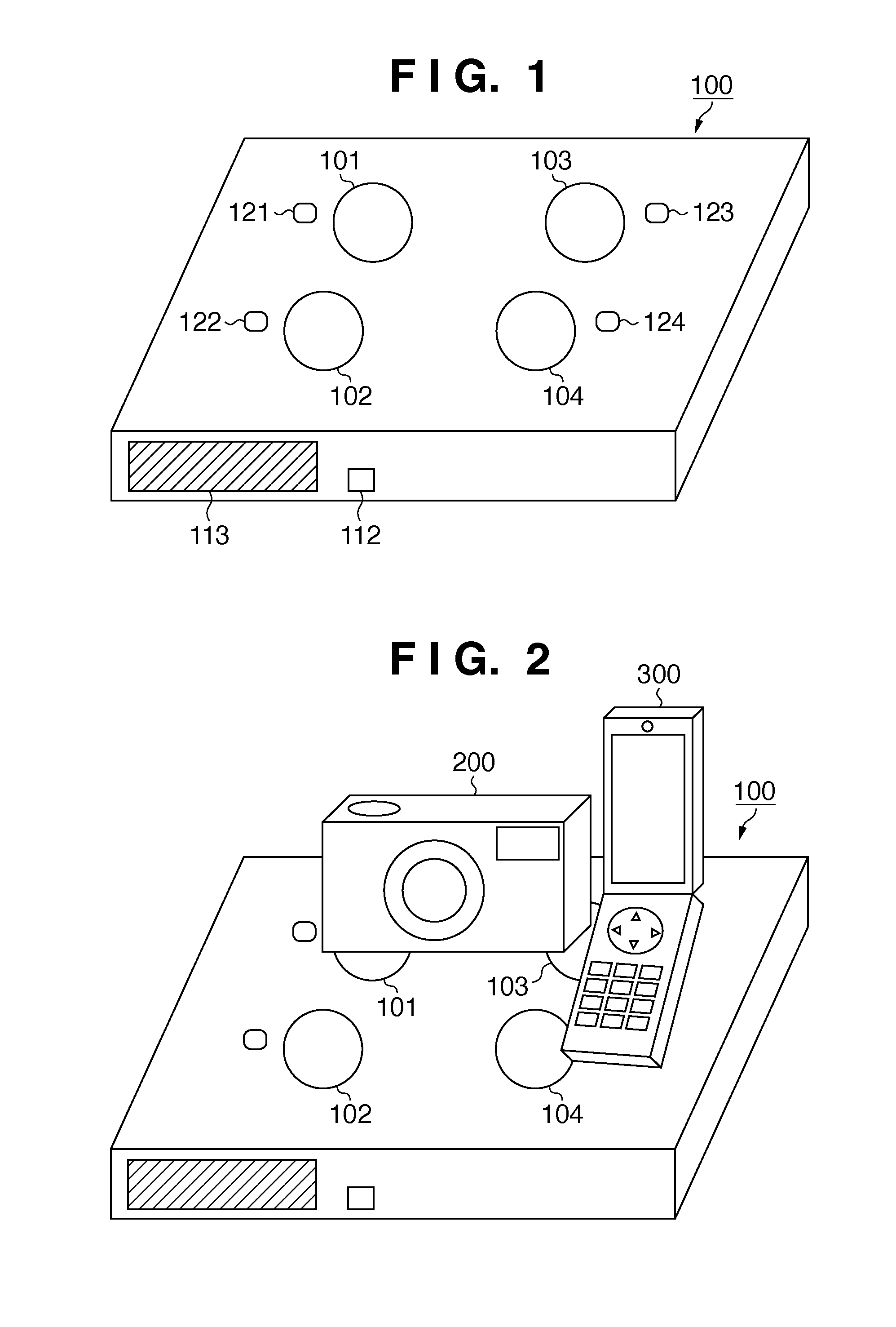
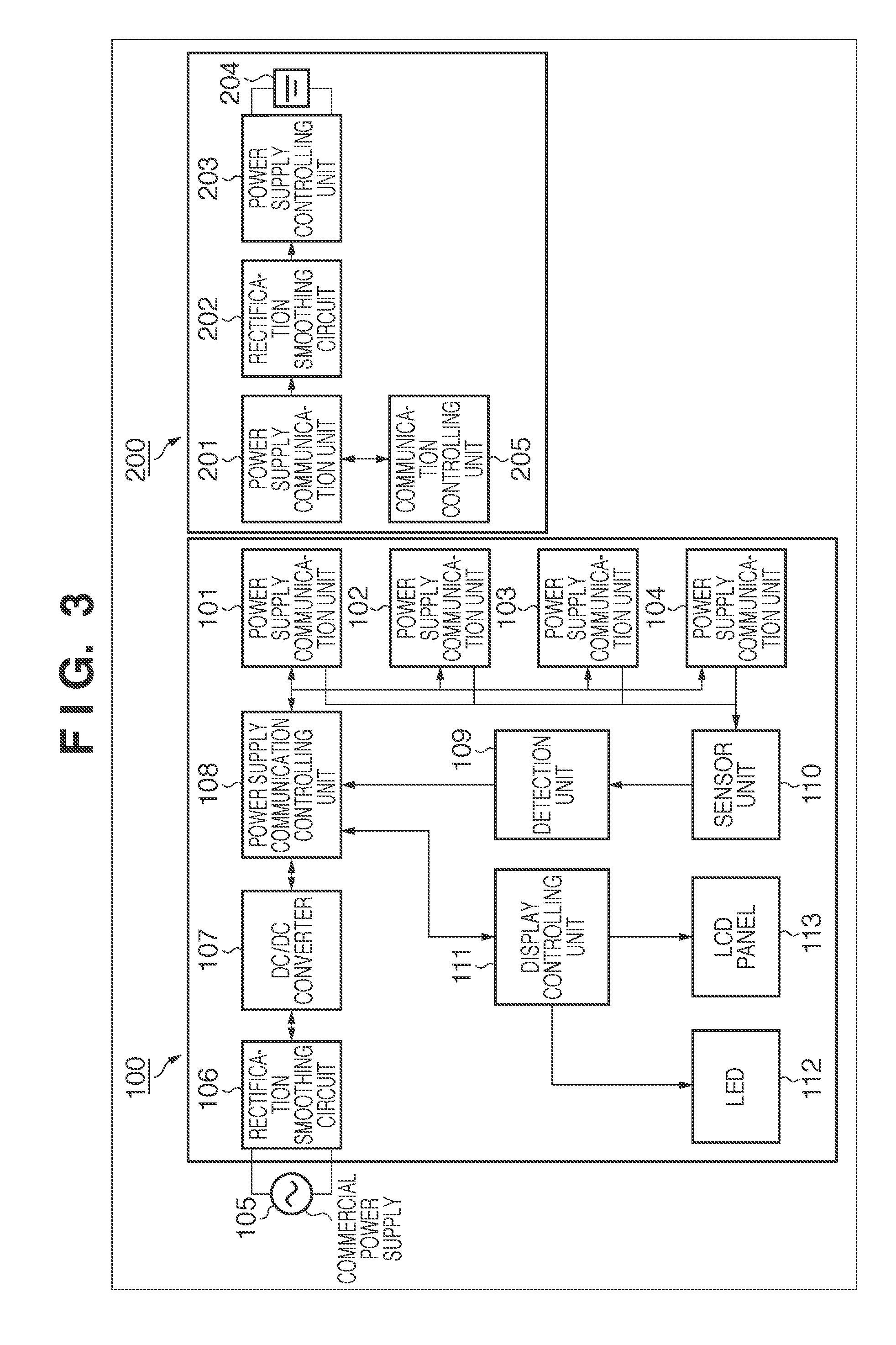
[0016]FIG. 1 is a perspective view showing the external arrangement of a non-contact type power-supplying device 100 according to this embodiment. As shown in FIG. 1, the power-supplying device 100 includes power supply communication units 101 to 104 each having a power supply function and a communication function. That is, the power-supplying device 100 includes a plurality of power supply communication units each having one primary coil for supplying power to an external device having a secondary coil. The power-supplying device 100 supplies power, in a non-contact manner, to external devices set in the magnetic fields (power supply areas) generated by the primary coils of the four power supply communication units b...


PUM


Abstract

Even when power is to be simultaneously supplied to a plurality of power-supplied devices by using one primary coil, it is possible to properly supply power to the respective power-supplied devices. More specifically, a power-supplying device stops non-contact power supply in accordance with the detection of a plurality of power-supplied devices set in a power supply area.

Description

TECHNICAL FIELD[0001]The present invention relates to a power-supplying device, a control method for the same, and a power-supplying system.BACKGROUND ART[0002]Conventionally, there has been known a power-supplying device that supplies power to a power-supplied device in a non-contact manner by using electromagnetic induction. Such a power-supplying device uses a mechanism to generate an electromotive force on the secondary coil side of a power-supplied device by feeding a current to the primary coil side. By using this electromagnetic induction to supply power, the displacement between the primary coil and the secondary coil will become the less power efficiency or cause excessive power supply. For this reason, Japanese Patent Laid-Open No. 9-103037 discloses a method to control the power to be supplied, based on the information received from a power-supplied device.[0003]The above conventional technique, however, is not based on the assumption that power is simultaneously supplied...

Claims


Application Information

Patent Timeline
IPC IPC(8): H01F38/14H02J7/00
CPCH01M10/44H01M10/48H02J7/025H04B5/0037H02J7/0013H02J7/027H02J7/042H02J5/005H02J50/90H02J7/007Y02E60/10H02J7/02H02J7/00302H02J7/0049H02J50/12H02J50/40H02J50/80H02J7/00045H02J7/00034H02J7/00036H02J7/00041H02J7/00
Inventor TANABE, AKIHIRO
Owner CANON KK
Why Eureka
Try Eureka