Radial deployment surgical tool

Active Publication Date: 2011-12-01
SURGALIGN SPINE TECH INC
View PDF6 Cites 76 Cited by
  • Summary
  • Abstract
  • Description
  • Claims
  • Application Information

AI Technical Summary

Problems solved by technology

While it is generally desirable to perform surgical procedures where the surgeon can directly see the area where the surgical procedure is being performed, this procedure is generally only suitable for surgical procedures that are close to a person's skin because providing an opening that is sufficiently large to view a surgical location that is located deeper within the person's body could require cutting of additional tissue and other components within the person's body.
Such additional cutting raises the potential of the patient experiencing a longer recovery time as well as being subjected to an increased likelihood of complications from the surgery.
While this technique is suitable for use in

Method used


Image

  • Radial deployment surgical tool
  • Radial deployment surgical tool
  • Radial deployment surgical tool

Examples


Embodiment Construction

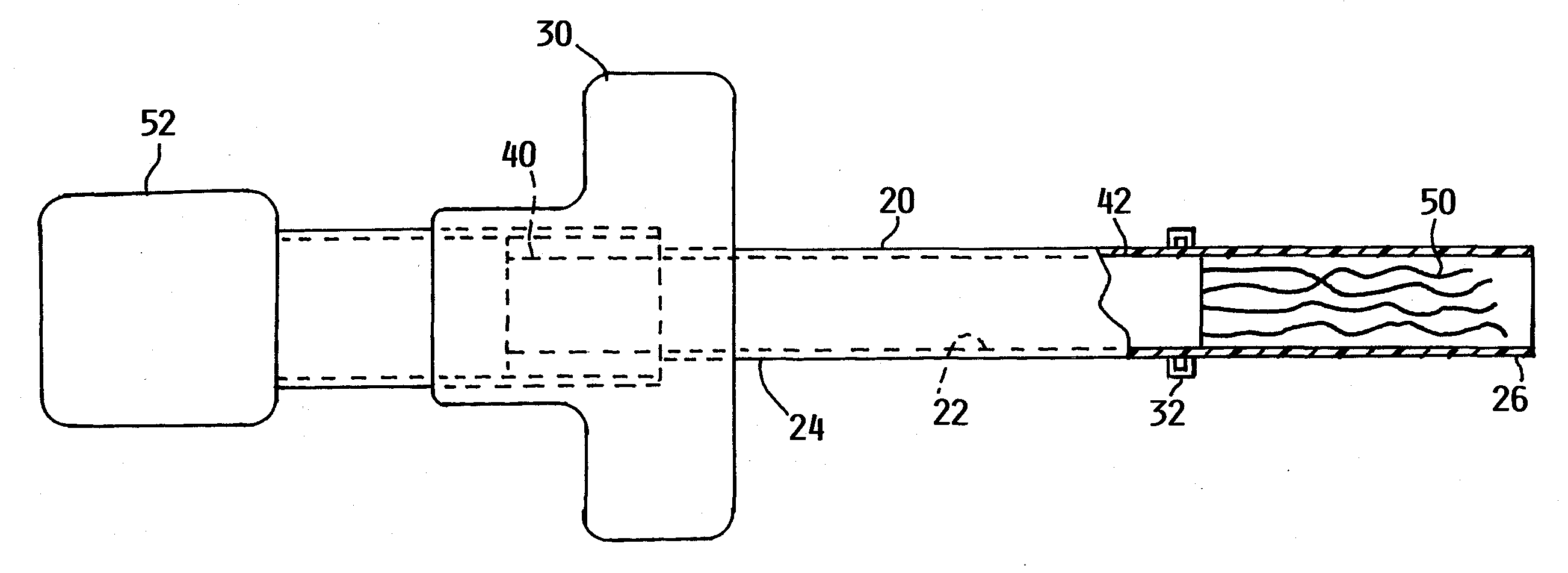
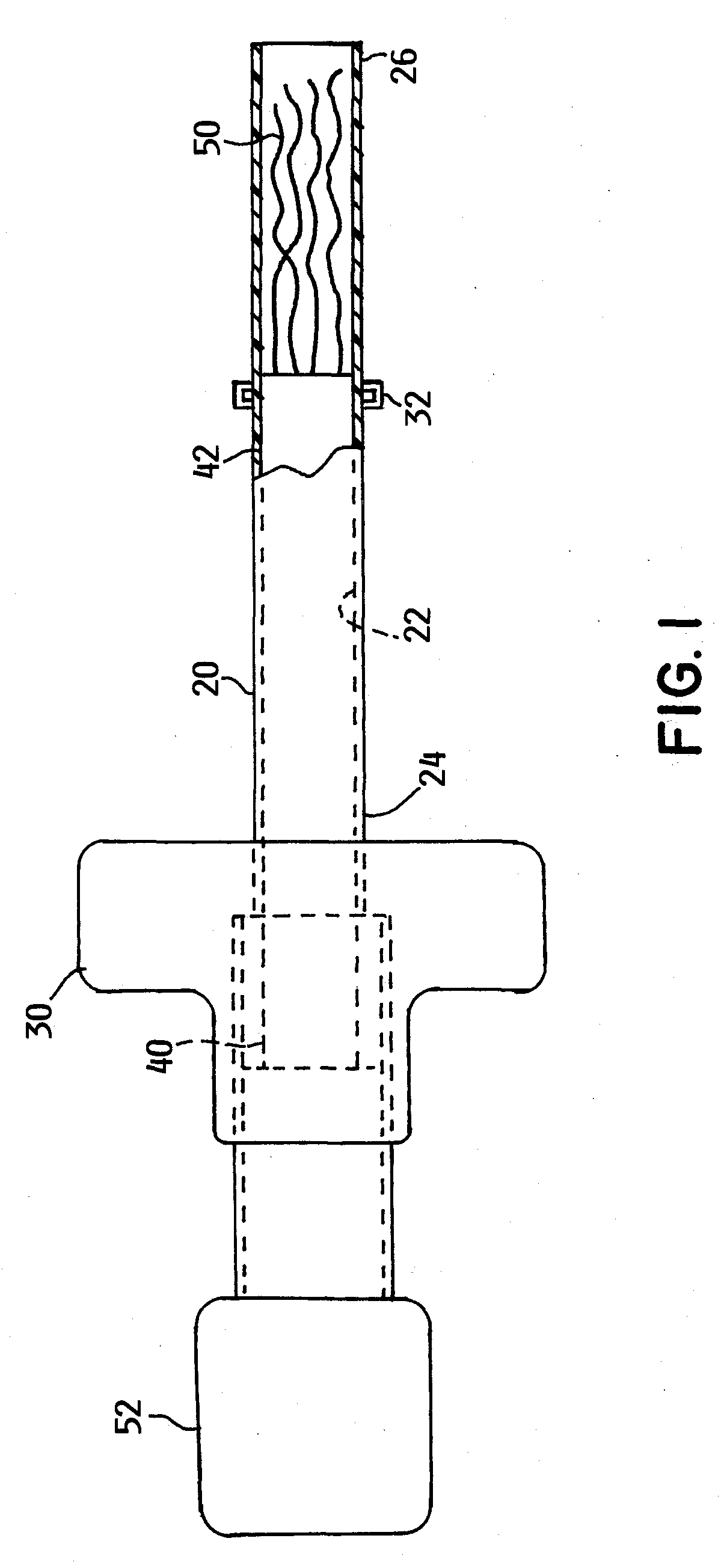
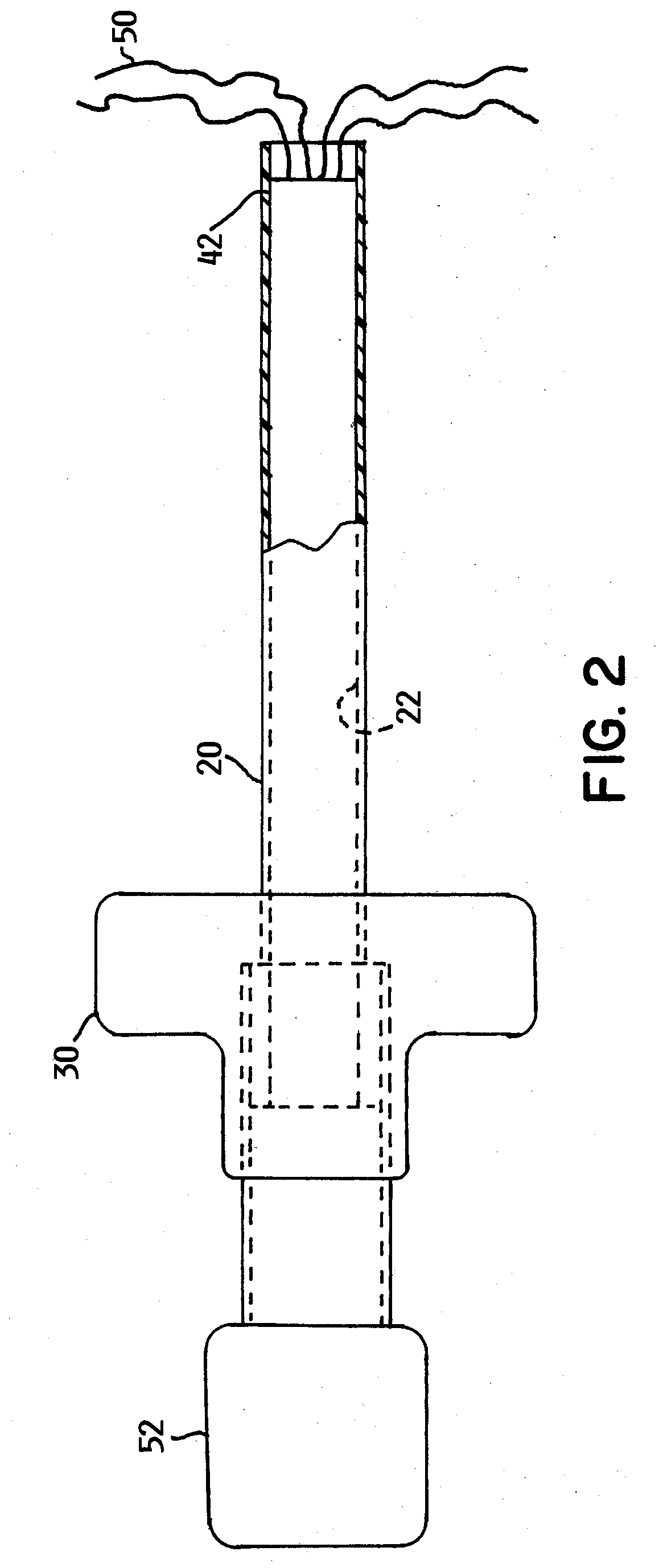
[0027]An embodiment of the invention is directed to a radial deployment surgical tool. The radial deployment surgical tool enables surgical procedures to be performed in relatively narrow spaces. As used herein, the term relatively narrow means spaces having a width of less than about ½ of an inch. In certain embodiments, the width of the space is less than about ⅛ of an inch.

[0028]The radial deployment surgical tool may be used in a variety of surgical settings. To facilitate using the radial deployment surgical tool in the variety of surgical settings, the radial deployment surgical tool may include a functional head attached to a distal end thereof.

[0029]One such suitable surgical setting is forming an opening between two bones that are located proximate each other. In an example of one such suitable surgical procedure is a minimally invasive orthopedic procedure. In this configuration, the functional head may be a cutting head that is attached to a distal end of the radial deplo...


PUM


Abstract

A radial deployment surgical tool having an inner shaft, an outer shaft and a function head. The radial deployment surgical tool is adapted for performing surgical procedures within narrow regions within a patient.

Description

REFERENCE TO RELATED APPLICATION[0001]This application claims priority to U.S. Provisional Application No. 61 / 349,303, which was filed on May 28, 2010, the contents of which are incorporated herein by reference.FIELD OF THE INVENTION[0002]An embodiment of the invention is directed to a surgical tool. More particularly, the invention relates to a radial deployment surgical tool that is adapted for performing surgical procedures within narrow regions within a patient.BACKGROUND OF THE INVENTION[0003]While it is generally desirable to perform surgical procedures where the surgeon can directly see the area where the surgical procedure is being performed, this procedure is generally only suitable for surgical procedures that are close to a person's skin because providing an opening that is sufficiently large to view a surgical location that is located deeper within the person's body could require cutting of additional tissue and other components within the person's body. Such additional ...

Claims


Application Information

Patent Timeline
IPC IPC(8): A61B17/50
CPCA46B7/023A61B17/1617A61B2017/320064A61B17/320725A61B2017/22079A61B17/32002A61B17/50A61B17/56A61B17/32A61B17/16
Inventor ASSELL, ROBERTBERG, THOMAS GODFREY
Owner SURGALIGN SPINE TECH INC
Why Eureka
Try Eureka