Multi-color reticle for ballistic aiming

a multi-color, ballistic aiming technology, applied in the direction of aiming means, weapons, sighting devices, etc., can solve the problems of affecting the acquisition and visibility of targets, time-consuming adjustment of elevation and windage, and affecting the effect of windage adjustmen

Active Publication Date: 2011-12-08
LEUPOLD & STEVENS
View PDF0 Cites 60 Cited by
  • Summary
  • Abstract
  • Description
  • Claims
  • Application Information

AI Technical Summary

Problems solved by technology

Adjustment of the elevation and windage is time consuming and may require the shooter to take his or her eyes off the target while manipulating the adjustment mechanisms or measurement tools.
First, they tend to clutter the field of view, which can inhibit target acquisition and visibility.
Second, the number of different discrete ranges for which there are secondary aiming marks is limited and for ranges falling in between those corresponding to the secondary aiming marks, the user must interpolate or guesstimate as to the proper holdover.
A similar issue applies to windage adjustments.

Method used


Image

  • Multi-color reticle for ballistic aiming
  • Multi-color reticle for ballistic aiming
  • Multi-color reticle for ballistic aiming

Examples


Embodiment Construction

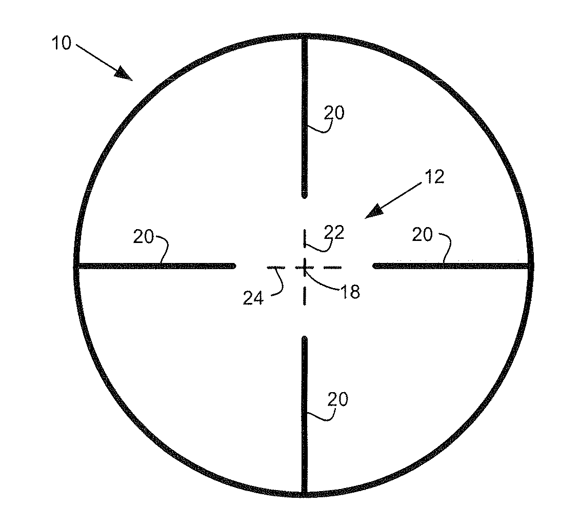
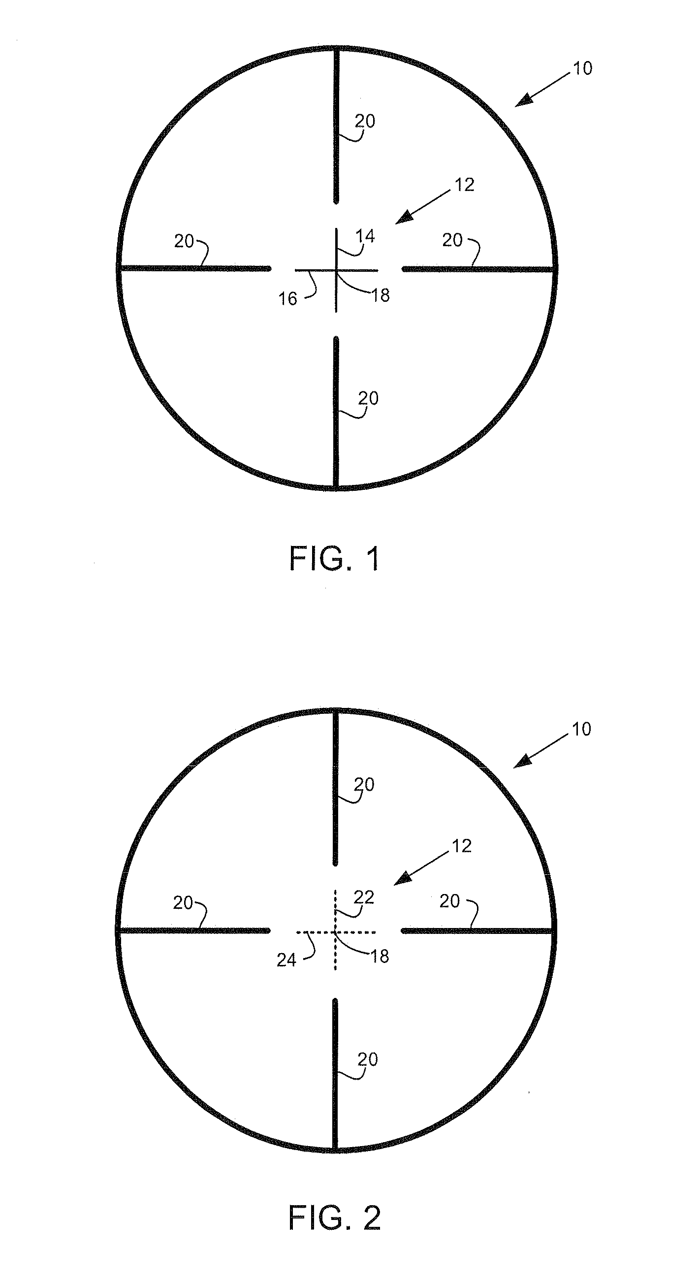
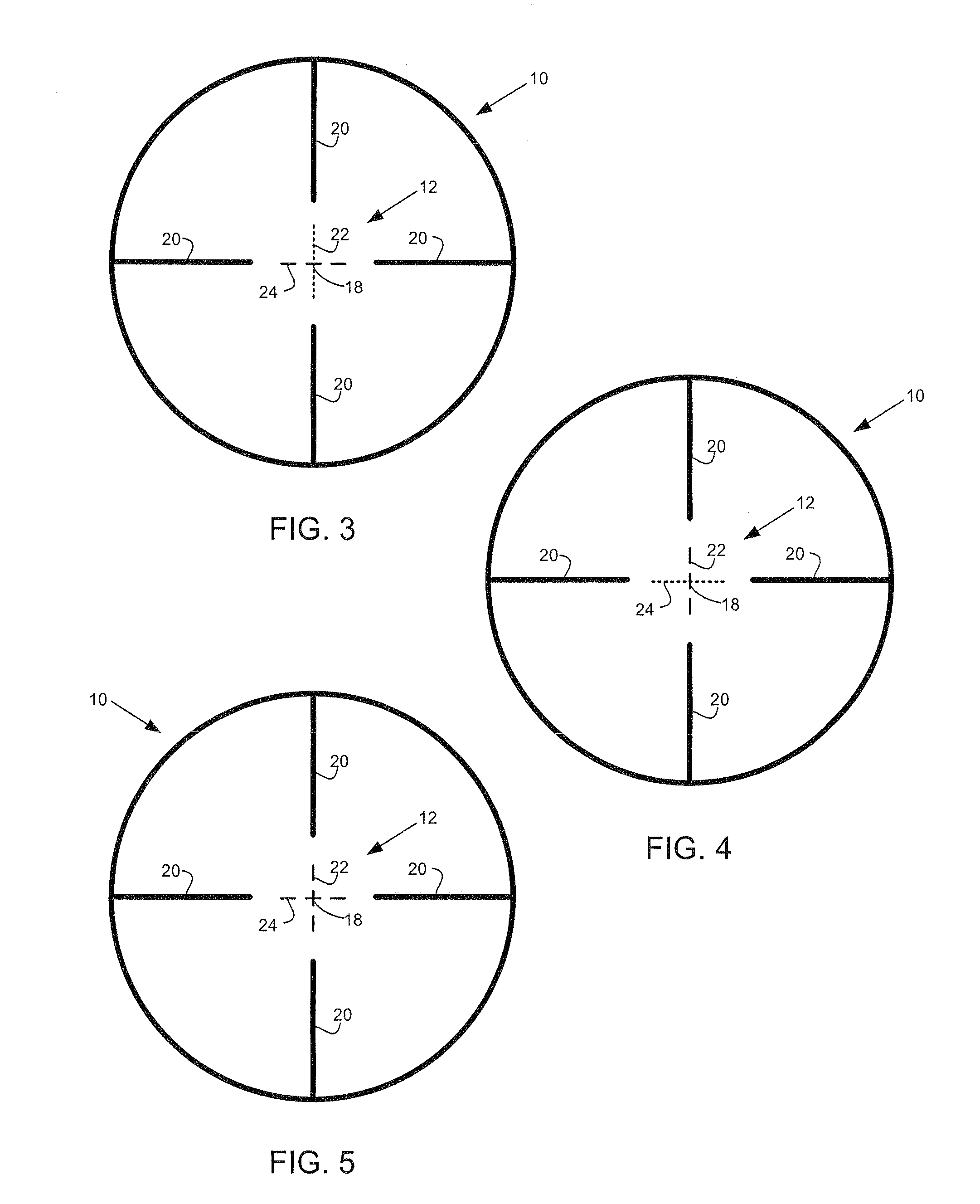
According to one embodiment, a projectile weapon aiming system such as a riflescope, may include a computer-controllable illuminated reticle with crosshairs or other aiming marks having an illumination color that can be selectively changed to provide feedback to a shooter to indicate when the aiming device (and hence the weapon itself) is accurately aimed at a target to compensate for a particular range, inclination, and other ballistic conditions (e.g., the initial velocity of the projectile, the altitude of the projectile weapon above sea level, the barometric pressure, the ambient temperature, the relative humidity, the height of the projectile weapon aiming system above a bore line of the projectile weapon, a compass heading of a line of site, or a geographic location of the projectile weapon). As used herein, target refers to a desired point of impact of the projectile.

The reticle may include any of a variety of known or future-developed technologies for displaying colored and / ...


PUM


Abstract

According an embodiment, a projectile weapon aiming system includes a computer-controllable reticle with crosshairs or other aiming marks having a color and/or illumination that can be selectively changed to provide feedback to a shooter to indicate when the projectile weapon aiming system (and hence the projectile weapon itself) is accurately aimed to compensate for a particular range, inclination, crosswind, and/or other ballistic conditions.

Description

TECHNICAL FIELDThis application relates to projectile weapon aiming systems, to reticle configurations for projectile weapon aiming systems, and to aiming and ballistic adjustment methods generally.BACKGROUNDProjectile weapon aiming systems are discussed herein principally with reference to their use on rifles and embodied in telescopic sights commonly known as riflescopes. It will become apparent, however, that projectile weapon aiming systems may include aiming devices other than riflescopes, such as reflex sights and bow sights for example, and may be used on weapons other than rifles, which are capable of propelling projectiles along substantially predeterminable initial trajectories, e.g., handguns, shotguns, bows, crossbows, artillery, and the like.A factor that must be taken into account in long-range shooting is the curved trajectory traversed by a bullet or other projectile as it falls from its initial trajectory while traveling the distance from the projectile weapon to th...

Claims


Application Information

Patent Timeline
Patent Type & Authority Applications(United States)
IPC IPC(8): F41G1/00F41G3/06F41G3/08
CPCF41G1/38
Inventor YORK, ANDREW W.
Owner LEUPOLD & STEVENS
Why Eureka
Try Eureka