Method of manufacturing near-field light generator including waveguide and plasmon generator

a generator and waveguide technology, applied in the field of manufacturing a near-field light generator, can solve the problems of increasing the coercivity of the recording medium, reducing the thermal stability of the magnetization of the magnetic fine particles, and difficult to perform data writing with the existing magnetic head, so as to reduce the variation in distance

a generator and waveguide technology, applied in the field of manufacturing a near-field light generator, can solve the problems of increasing the coercivity of the recording medium, reducing the thermal stability of the magnetization of the magnetic fine particles, and difficult to perform data writing with the existing magnetic head, so as to reduce the variation in distance

US20110303637A1Active Publication Date: 2011-12-15HEADWAY TECH INC

Image

  • Method of manufacturing near-field light generator including waveguide and plasmon generator
  • Method of manufacturing near-field light generator including waveguide and plasmon generator
  • Method of manufacturing near-field light generator including waveguide and plasmon generator

Examples


first embodiment

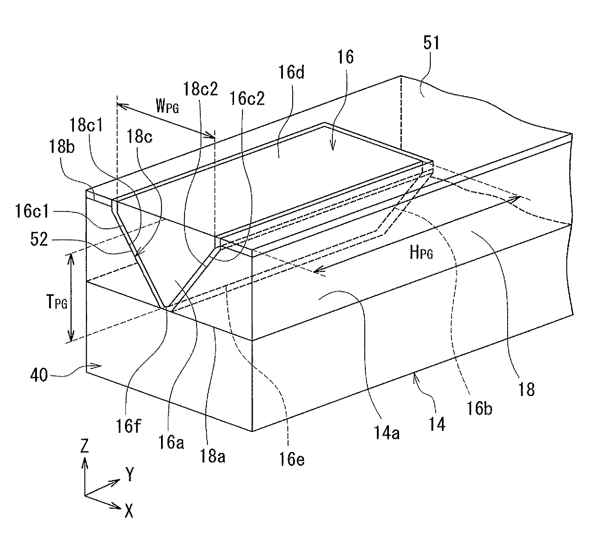
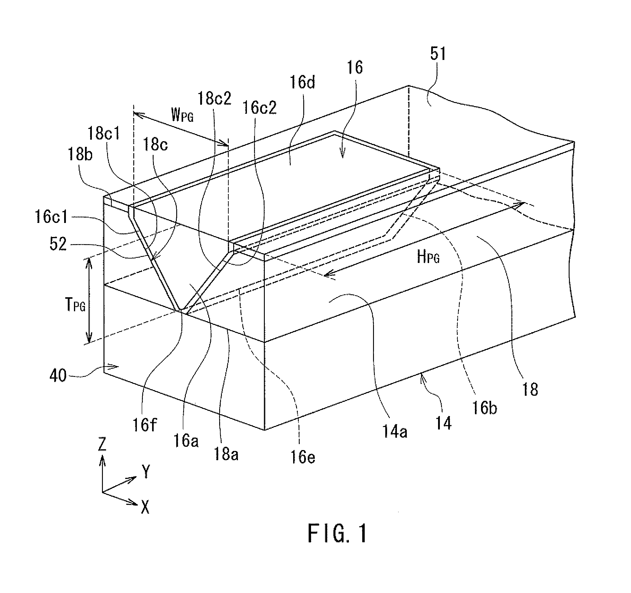
[0053]Preferred embodiments of the present invention will now be described in detail with reference to the drawings. First, reference is made to FIG. 1 to FIG. 6 to describe the configuration of a thermally-assisted magnetic recording head according to a first embodiment of the invention. FIG. 1 is a perspective view showing the main part of the thermally-assisted magnetic recording head. FIG. 2 is a front view showing a part of the medium facing surface of the thermally-assisted magnetic recording head. FIG. 3 is a cross-sectional view showing the configuration of the thermally-assisted magnetic recording head. FIG. 4 is a front view showing the medium facing surface of the thermally-assisted magnetic recording head. FIG. 5 is a plan view showing a first layer of a coil of the thermally-assisted magnetic recording head. FIG. 6 is a plan view showing a second layer of the coil of the thermally-assisted magnetic recording head.

[0054]The thermally-assisted magnetic recording head acco...

second embodiment

[0119]A thermally-assisted magnetic recording head according to a second embodiment of the invention will now be described with reference to FIG. 14 to FIG. 16. FIG. 14 is a perspective view showing the main part of the thermally-assisted magnetic recording head according to the present embodiment. FIG. 15 is a front view showing a part of the medium facing surface of the thermally-assisted magnetic recording head according to the present embodiment. FIG. 16 is a magnified partial front view of the plasmon generator shown in FIG. 15.

[0120]The thermally-assisted magnetic recording head according to the present embodiment has a plasmon generator 66 and a clad layer 68 instead of the plasmon generator 16 and the clad layer 18 of the first embodiment. The near-field light generator according to the present embodiment has the waveguide 14, the clad layer 68, the plasmon generator 66, and the dielectric film 52. The plasmon generator 66 is made of the same material as that of the plasmon ...


PUM


Abstract

A near-field light generator includes: a waveguide; a clad layer having a penetrating opening and disposed on the waveguide; a plasmon generator accommodated in the opening; and a dielectric film interposed between the plasmon generator and each of the waveguide and the clad layer. In a method of manufacturing the near-field light generator, an initial clad layer is initially formed on the waveguide, and then the initial clad layer is taper-etched by RIE to form a recess that does not reach the top surface of the waveguide. Subsequently, the recess is etched by wet etching until the top surface of the waveguide is exposed in part. Next, the dielectric film is formed in the opening, and the plasmon generator is formed on the dielectric film.

Description

BACKGROUND OF THE INVENTION[0001]1. Field of the Invention[0002]The present invention relates to a method of manufacturing a near-field light generator for use in thermally-assisted magnetic recording where a recording medium is irradiated with near-field light to lower the coercivity of the recording medium for data writing.[0003]2. Description of the Related Art[0004]Recently, magnetic recording devices such as magnetic disk drives have been improved in recording density, and thin-film magnetic heads and recording media of improved performance have been demanded accordingly. Among the thin-film magnetic heads, a composite thin-film magnetic head has been used widely. The composite thin-film magnetic head has such a structure that a read head including a magnetoresistive element (hereinafter, also referred to as MR element) for reading and a write head including an induction-type electromagnetic transducer for writing are stacked on a substrate. In a magnetic disk drive, the thin-f...

Claims


Application Information

Patent Timeline
15 Dec 2011
Publication
US20110303637A1
IPC
B05D5/06; G02B6/02
CPC
G02B6/1226; B82Y20/00
Inventors
ARAKI, HIRONORI; SASAKI, YOSHITAKA