
Vehicle Presence Notification Apparatus

a technology for vehicle presence and notification apparatus, which is applied in the direction of vehicle position/course/altitude control, using reradiation, instruments, etc., can solve the problems of increasing the difficulty of vehicle attachment, increasing the weight of the vehicle, increasing costs, etc., and reducing costs. , the effect of reducing the low-pitched sound and reducing the cos

Active Publication Date: 2011-12-15
DENSO ELECTRONICS CORP
View PDF3 Cites 24 Cited by
  • Summary
  • Abstract
  • Description
  • Claims
  • Application Information

AI Technical Summary

Benefits of technology

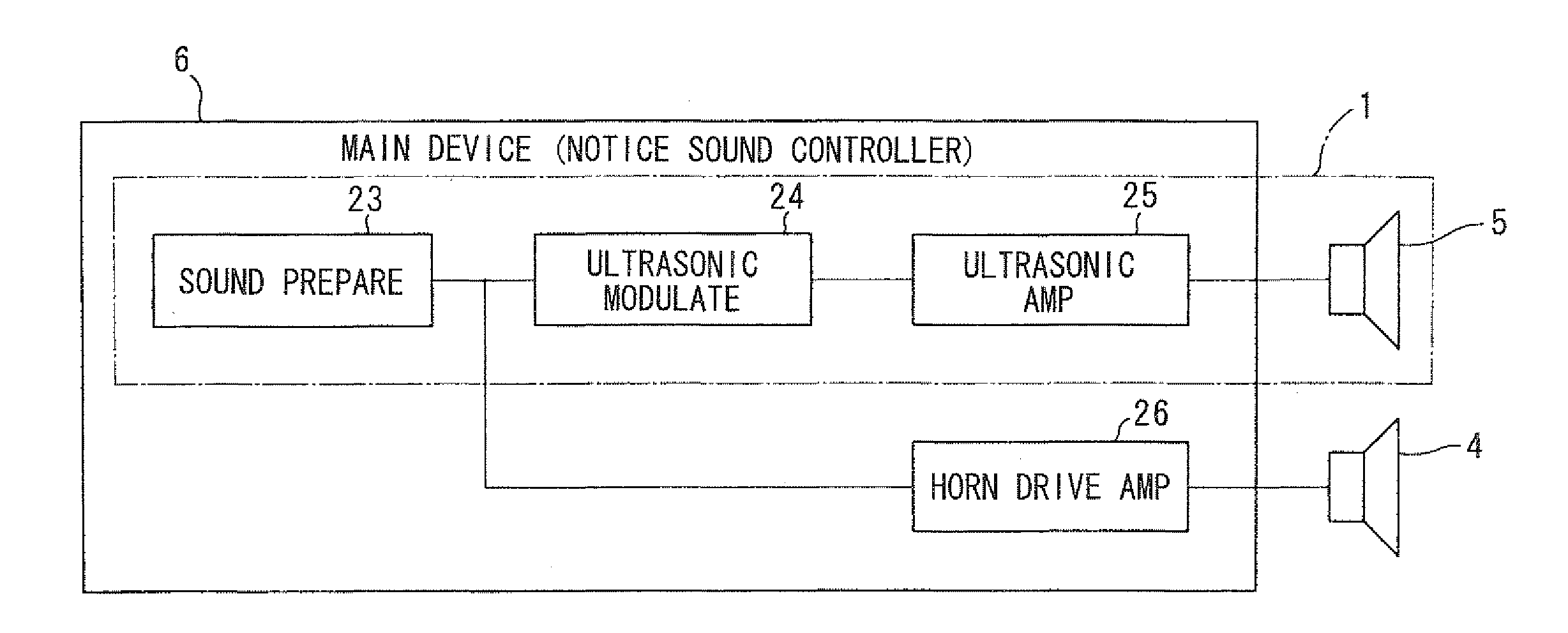
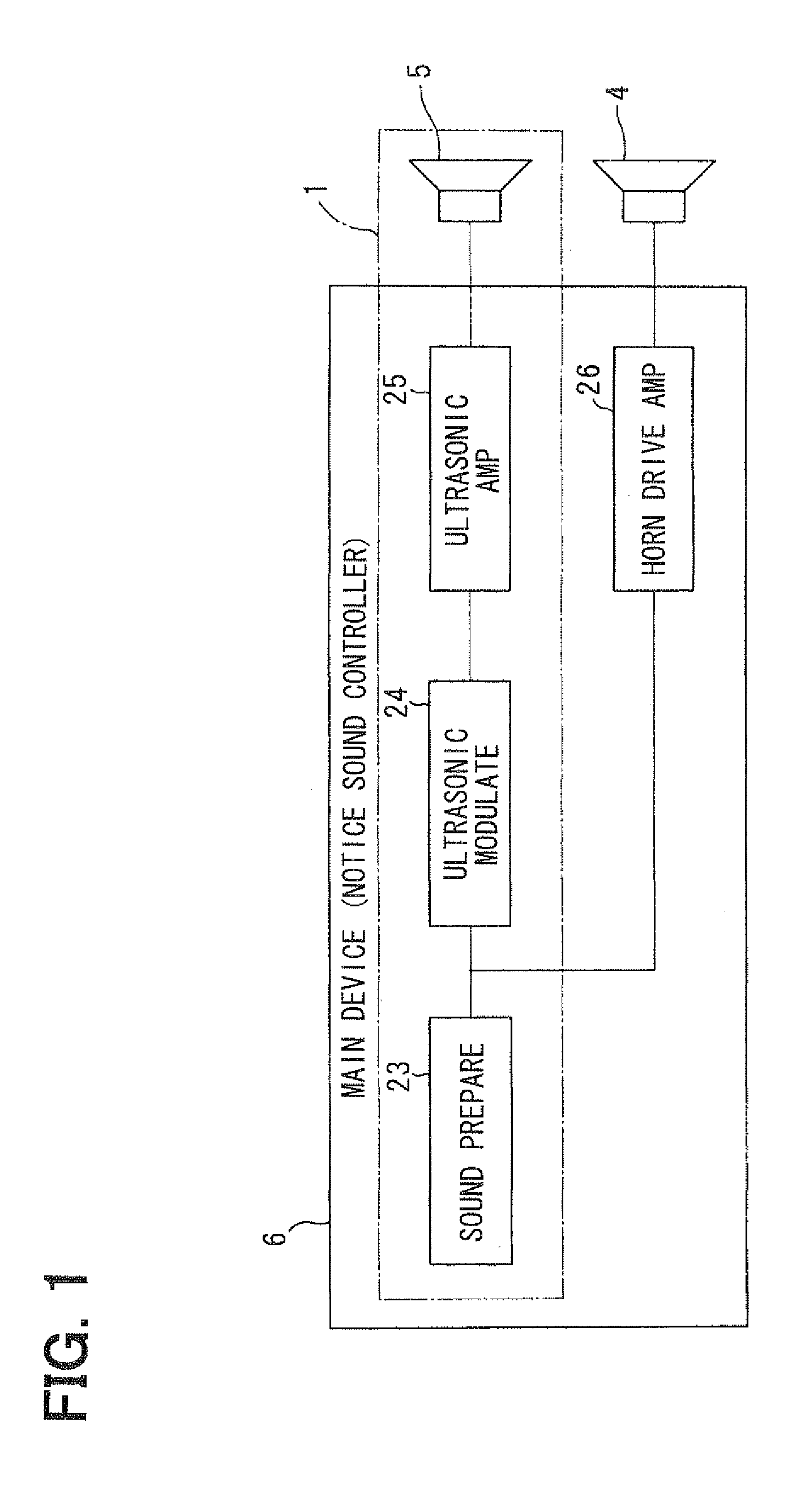
Thus, the combination of the parametric speaker device and the vehicular horn device used as a dynamic speaker complements the shortage of the low-pitched sound in a vicinity of the vehicle mounting the parametric speaker device with the vehicular horn device serving as a dynamic speaker. Therefore, the vehicle need not mount a dynamic speaker using a large-sized cone type vibrating plate that is good at reproducing a low-pitched sound. Even in a range near the vehicle, while the shortage of the low-pitched sound of the false engine sound can be suppressed, the false engine sound can be generated so as to model for a real engine sound.
In addition, the vehicular horn device having an existing structure is used for complementing the shortage of the low-pitched sound pertinent to the parametric speaker device, thereby reducing costs and helping prevent a problem to be mounted in a vehicle. Furthermore, the vehicle presence notification apparatus uses or shares the vehicular horn device that is basically provided in a vehicle to output an alarm sound by a horn switch; thus, there is no need to additionally or separately mount a device or speaker in the vehicle so as to complement the shortage of the low-pitched sound, reducing costs and removing a need of securing a mounting space.
As a vehicle (or ultrasonic wave speaker) approaches a pedestrian, the low-pitched sound of a false engine sound by the vehicular horn device increases. In other words, as a vehicle approaches a pedestrian, the low-pitched sound reproduced by the vehicular horn device increases and the sound quality or sound tone of the false engine sound heard by the pedestrian varies. Thus, as the vehicle approaches the pedestrian, the low-pitched sound in the false engine sound increases to change the sound tone of the false engine sound; thus, the pedestrian easily notices the false engine sound, increasing a probability for the pedestrian to know the presence of the vehicle.

Problems solved by technology

Such a vehicle is not easily noticed by a pedestrian, posing a problem.
In this regard, however, such a proposal poses a problem A1, such as increasing a difficulty in attachment in the vehicle, increasing a weight of the vehicle, or increasing costs.
This poses another problem A2.
That is, due to the above problem A2, a shortage of the low-pitched sound arises in a false engine sound reproduced by the parametric speaker device in a vicinity of the vehicle.
This provides a hindrance to the purpose of making the false engine sound using the parametric speaker device have frequency levels identical to those of the real engine sound.
Furthermore, when a notice sound having a larger sound pressure is emitted from the dynamic speaker mounted in the vehicle, a vehicle occupant who is in the vehicle continuously has to hear the notice sound emitted from the dynamic speaker for a long time depending on the sound pressure.
To that end, if reducing an output level of the dynamic speaker in order to lower a sound pressure of the notice sound which the vehicle occupant hears down to the limit of the vehicle occupant's sensitivity, the propagation distance of the notice sound becomes shorter, making it impossible to send the notice sound to the target propagation distance.

Method used


Image

  • Vehicle Presence Notification Apparatus
  • Vehicle Presence Notification Apparatus
  • Vehicle Presence Notification Apparatus

Examples


first embodiment

Modification of First Embodiment

A modification of the first embodiment will be explained with reference to FIG. 11. The modification of the first embodiment provides an ultrasonic directionality extension portion or means (expander). When a travel speed of the vehicle S is below a predetermined speed (at a slow vehicle speed), the ultrasonic directionality extension portion extends the directionality of the ultrasonic wave (directionality on a horizontal plane in the heading direction of the vehicle S), which the ultrasonic wave speaker 5 generates.

As illustrated in FIG. 11, the ultrasonic directionality extension portion extends a propagation region a of a false engine sound by the parametric speaker device 1 at a slow vehicle speed as compared with that in FIG. 10A of the first embodiment. (i) The propagation region a of the ultrasonic wave may be extended using several auxiliary piezoelectric speakers 21 arranged in an oblique direction on either right side and the left side with...

second embodiment

[Operation of Second Embodiment]

The operation of the vehicle presence notification apparatus of the second embodiment is almost identical to that of the first embodiment; thus, the explanation is omitted.

[Effect 1 of Second Embodiment]

The vehicle presence notification apparatus of the second embodiment adopts the above mentioned configuration, thereby providing the following effect.

(a) In a short distance region (0 m to 5 m) ahead of the vehicle S, a false engine sound by the dynamic speaker 4 (the one-dot chain line A of FIG. 13) and a false engine sound by the parametric speaker device 1 (the two-dot chain line B of FIG. 13) are combined, enabling the generation of the false engine sound having a high sound pressure (the solid line C of FIG. 13). Therefore, in the short distance region (0 m to 5 m) from the vehicle S to a pedestrian, a notice sound having a higher sound pressure can be provided to the pedestrian, thereby notifying the pedestrian of the presence of the vehicle S mo...


PUM


Abstract

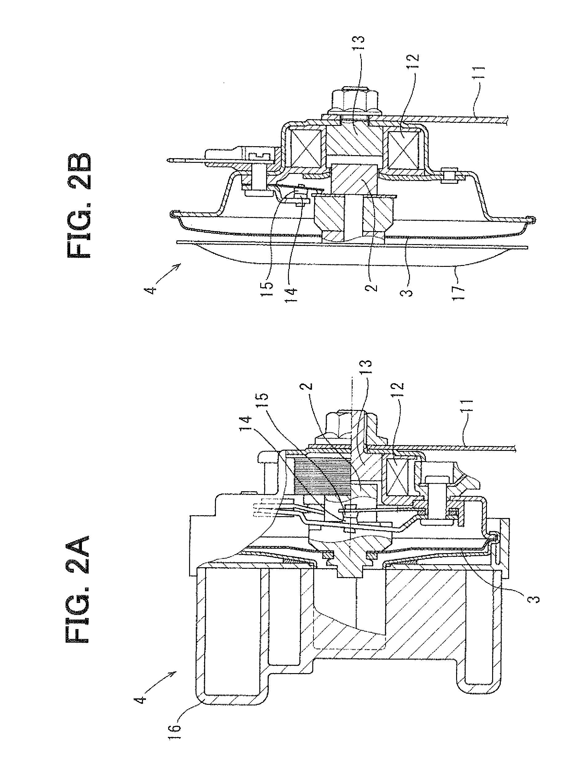
A vehicular horn device of an existing electromagnetic type is used as a dynamic speaker so as to generate a false engine sound. The shortage of a low-pitched sound in a parametric speaker device is complemented with a false engine sound which the vehicular horn device generates. Thereby, without need of mounting a large-sized dynamic speaker such as a woofer in a vehicle, a false engine sound is generated so as to model for a real engine sound. In addition, as the vehicle approaches a pedestrian, a sound tone of the false engine sound which the pedestrian hears changes, enabling the pedestrian to easily notice the approach or presence of the vehicle.

Description

CROSS REFERENCE TO RELATED APPLICATIONThe present application is based on and incorporates herein by reference Japanese Patent Application No. 2010-132107 filed on Jun. 9, 2010 and Japanese Patent Application No. 2010-138449 filed on Jun. 17, 2010.FIELD OF THE INVENTIONThe present invention relates to a vehicle presence notification apparatus that generates a notice sound such as a false engine sound outside of a vehicle to announce a presence of the vehicle in a vicinity of the vehicle. In particular, it relates to a technology suitably used in a vehicle driven by an electric motor which generates rotation power on electricity such as an electric vehicle, a fuel cell vehicle, or a hybrid vehicle.BACKGROUND OF THE INVENTION[Patent document 1] JP 2005-289175 AThere is a vehicle outputting a small traveling sound such as a vehicle driven on electric motor. Such a vehicle is not easily noticed by a pedestrian, posing a problem. To that end, there has been proposed a technology to cause...

Claims


Application Information

Patent Timeline
Patent Type & Authority Applications(United States)
IPC IPC(8): B60Q1/00
CPCB60Q5/008H04R1/403G10K15/02H04R2499/13H04R17/00
Inventor NAKAYAMA, TOSHIAKI
Owner DENSO ELECTRONICS CORP
Learn More