
Pixel driving circuit, pixel driving method and light emitting display device

Active Publication Date: 2011-12-15
E INK HLDG INC
View PDF7 Cites 17 Cited by
  • Summary
  • Abstract
  • Description
  • Claims
  • Application Information

AI Technical Summary

Benefits of technology

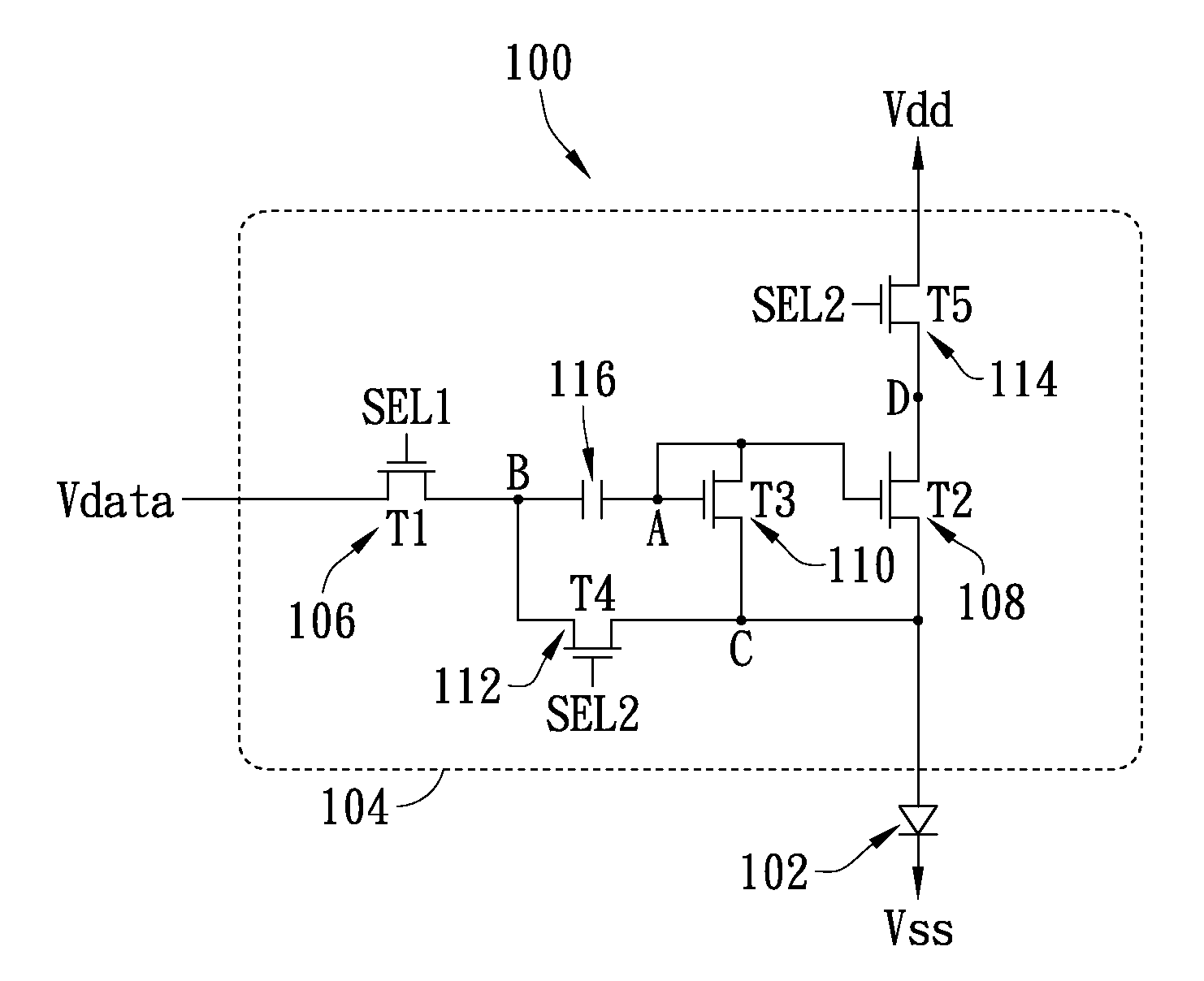
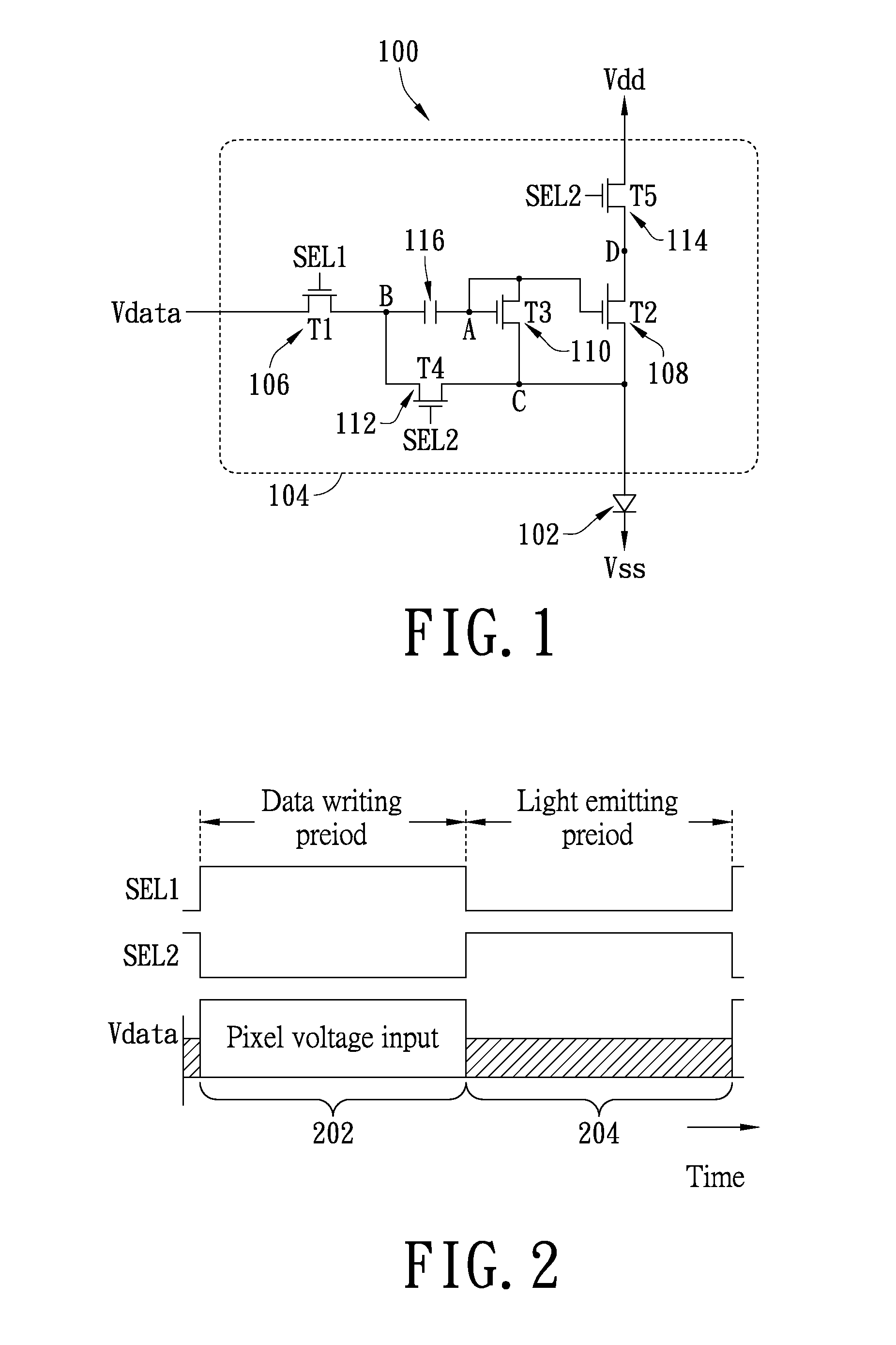
[0012]A light emitting display device in accordance with still another embodiment of the present invention is provided. Each of pixels of the light emitting display device can be provided with the above-mentioned pixel driving circuit and a LED. The light emitting display device further is equipped with a driving unit for driving each of the pixels thereof. In the present embodiment, the driving unit includes a

Problems solved by technology

In the application environment of modern manufacturing technology and the light emitting display device, as to the driving transistors of different pixels belonging to a same light emitting display device, threshold voltages of the driving transistors of the different pixels would occur drift variations along with the increase of working time, so that the brightness of the light emitting display device is uneven and thereby affecting the display quality of the light emitting display device.
In addition, as to the LEDs of the different pixels, threshold voltages thereof may occur drift variations along with aging, which would result in display characteristics of the light emitting display device being affected.

Method used


Image

  • Pixel driving circuit, pixel driving method and light emitting display device
  • Pixel driving circuit, pixel driving method and light emitting display device
  • Pixel driving circuit, pixel driving method and light emitting display device

Examples


Embodiment Construction

[0019]In the following detailed description of the preferred embodiments, reference is made to the accompanying drawings which form a part hereof, and in which are shown by way of illustration specific embodiments in which the invention may be practiced. It is to be understood that other embodiment may be utilized and structural changes may be made without departing from the scope of the present invention. Also, it is to be understood that the phraseology and terminology used herein are for the purpose of description and should not be regarded as limiting. The use of “including,”“comprising,” or “having” and variations thereof herein is meant to encompass the items listed thereafter and equivalents thereof as well as additional items. Unless limited otherwise, the terms “connected,”“coupled,” and “mounted,” and variations thereof herein are used broadly and encompass direct and indirect connections, couplings, and mountings. Accordingly, the descriptions will be regarded as illustra...


PUM


Abstract

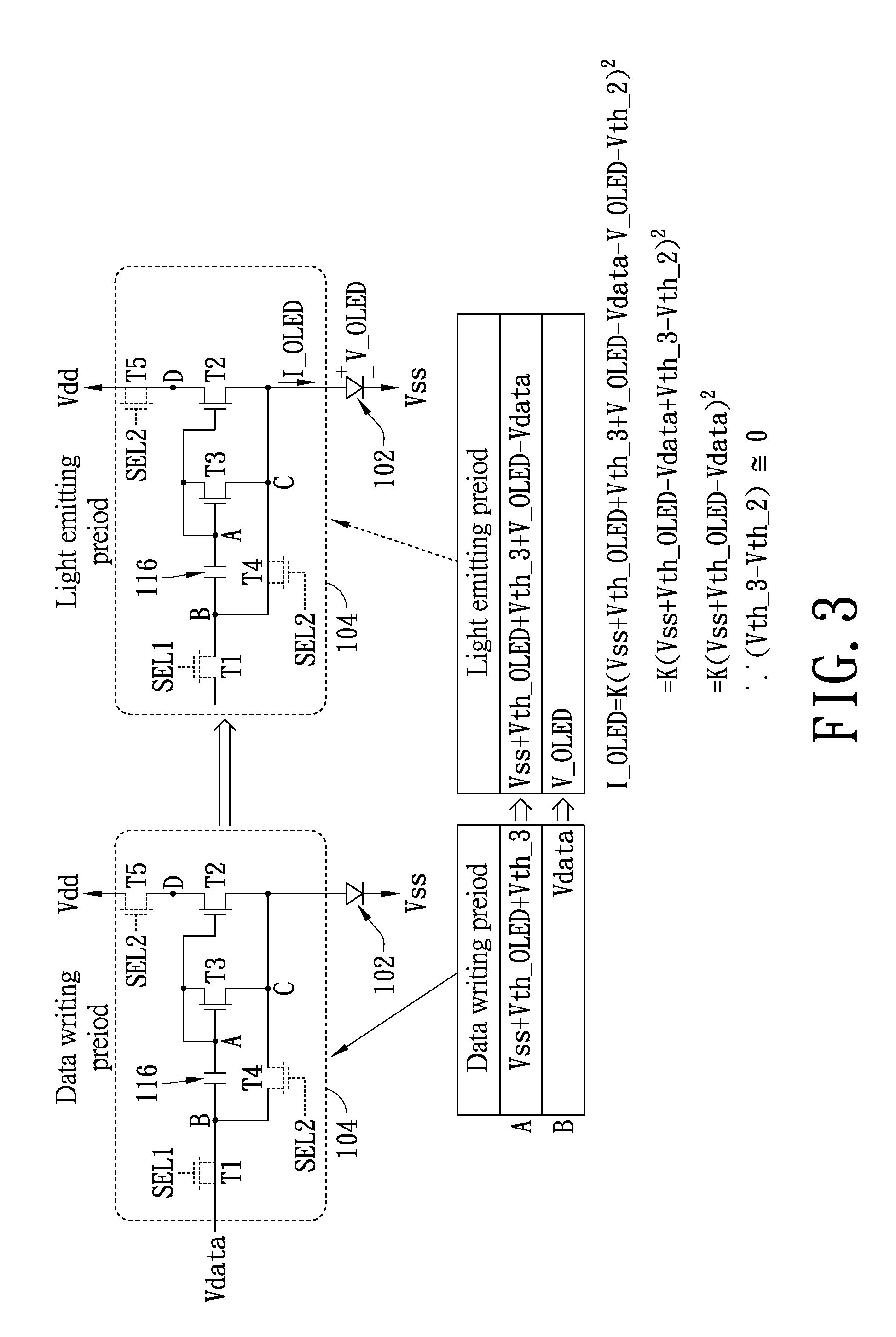
A pixel driving circuit, a pixel driving method and a light emitting display device are provided in the present invention. The pixel driving circuit includes first through fifth transistors and a capacitor and is for driving a light emitting diode. The third transistor forms a diode connection to make information of the threshold voltages of both the third transistor and the light emitting diode be stored in the capacitor in a data writing period. In a light emitting period, the second transistor compensates drift variation of the threshold voltages of the third transistor and the light emitting diode according to the information stored in the capacitor to provide a stable driving current for driving the light emitting diode.

Description

CROSS-REFERENCE TO RELATED APPLICATIONS[0001]This application is based upon and claims the benefit of priority from the prior Taiwan Patent Application No. 099118888, filed Jun. 10, 2010, the entire contents of which are incorporated herein by reference.BACKGROUND[0002]1. Technical Field[0003]The present invention generally relates to a pixel driving circuit, a pixel driving method and a light emitting display device and, particularly to a pixel driving circuit, a pixel driving method and a light emitting display device capable of compensating threshold voltage variations of a driving transistor and a light emitting diode (LED) in each pixel.[0004]2. Description of the Related Art[0005]Display devices are one of the most important man-machine interfaces in many modern electronic systems. Moreover, light emitting display devices whose pixels are constructed with LEDs (e.g., organic LEDs) have become one of the development mainstreams of the modern display device / panel technology.[000...

Claims


Application Information

Patent Timeline
IPC IPC(8): G09G5/00G09G3/36
CPCG09G3/3225G09G2320/045G09G2310/0262G09G2300/0814
Inventor HUANG, SUNG-HUISHINN, TED-HONGLAN, WEI-CHOULIN, CHIN-WEN
Owner E INK HLDG INC
Learn More