Rope-less jump rope simulator and resistance exercise device

a jump rope simulator and rope technology, applied in the field of exercise devices, can solve the problems of large noise, limited use of conventional jump rope, and inability of users who are not able to jump, and achieve the effects of providing wind resistance, reducing the impact of accidental strikes, and reducing nois

Inactive Publication Date: 2011-12-15
BORG UNLTD
View PDF5 Cites 19 Cited by
  • Summary
  • Abstract
  • Description
  • Claims
  • Application Information

AI Technical Summary

Benefits of technology

[0009]The device may include a mechanism for providing wind resistance and softening the impact of accidental strikes of the free end of the lash. The mechanism for providing wind resistance and softening the impact of accidental strikes of the free end of the lash may include a protective pad. The protective pad may include a foam ball or may include a gel-filled inner portion and a foam outer portion.

Problems solved by technology

For example, the use of the conventional jump rope is limited by the fact that a user must actually jump over the rope.
This is not possible for a user who is not able to jump (e.g., a person in a wheel chair, has a bad back, knees or the like) but who still wishes to obtain the benefits derived from jumping rope.
The use of a conventional jump rope can result in a user tripping over the rope and falling to the ground and can cause a great deal of noise as it is being used.
However, this jump rope still suffers from the same drawbacks as the conventional jump rope as there is still only a single rope interconnecting the two handles and thus requiring a user to have to jump over the rope in order to use the device.
However, the ball bearing assembly inside the handle to which the rope is attached provides only limited movement.
However, this device requires the use of electronics, a power supply, a display and the like.

Method used


Image

  • Rope-less jump rope simulator and resistance exercise device
  • Rope-less jump rope simulator and resistance exercise device
  • Rope-less jump rope simulator and resistance exercise device

Examples


Embodiment Construction

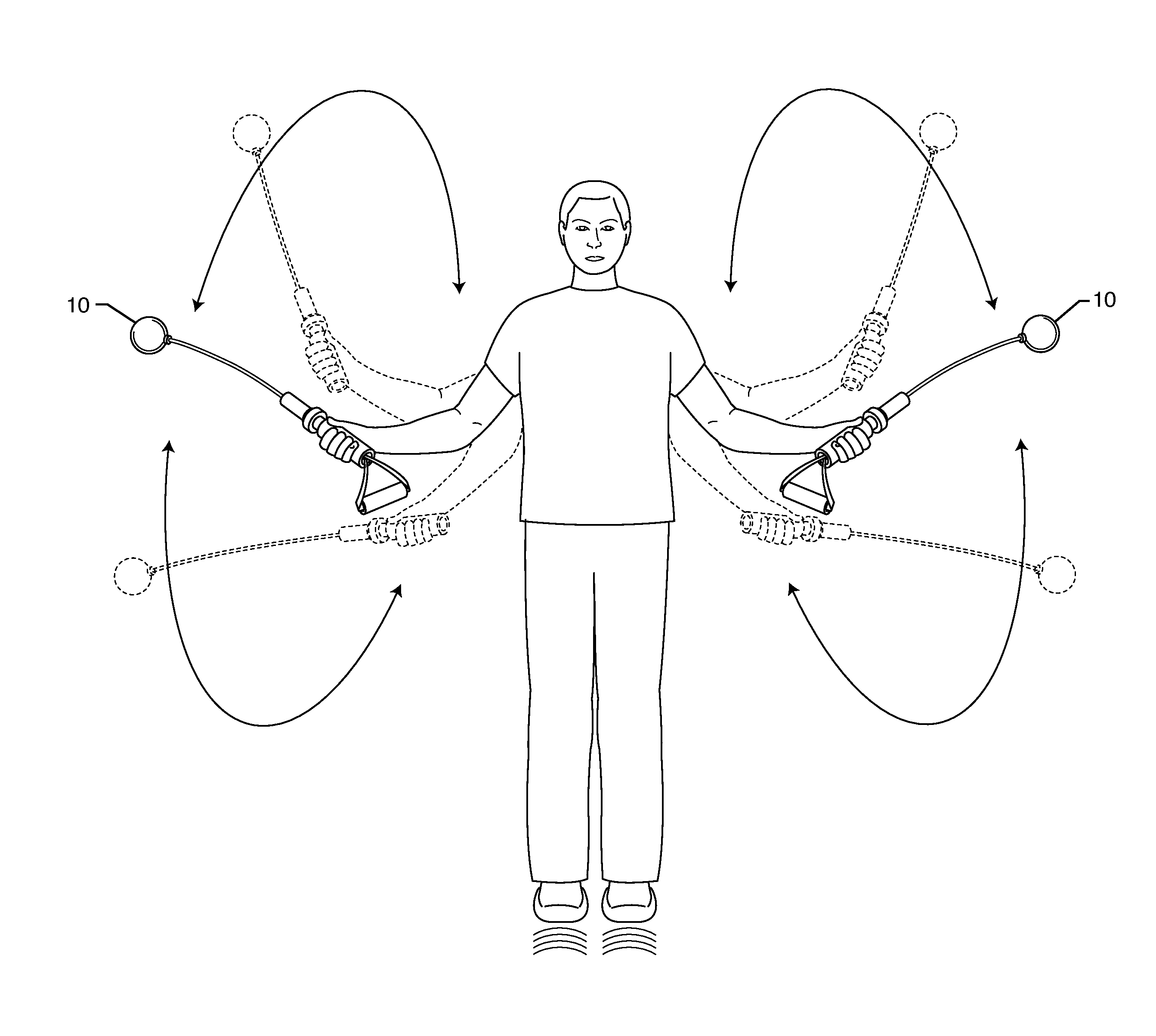
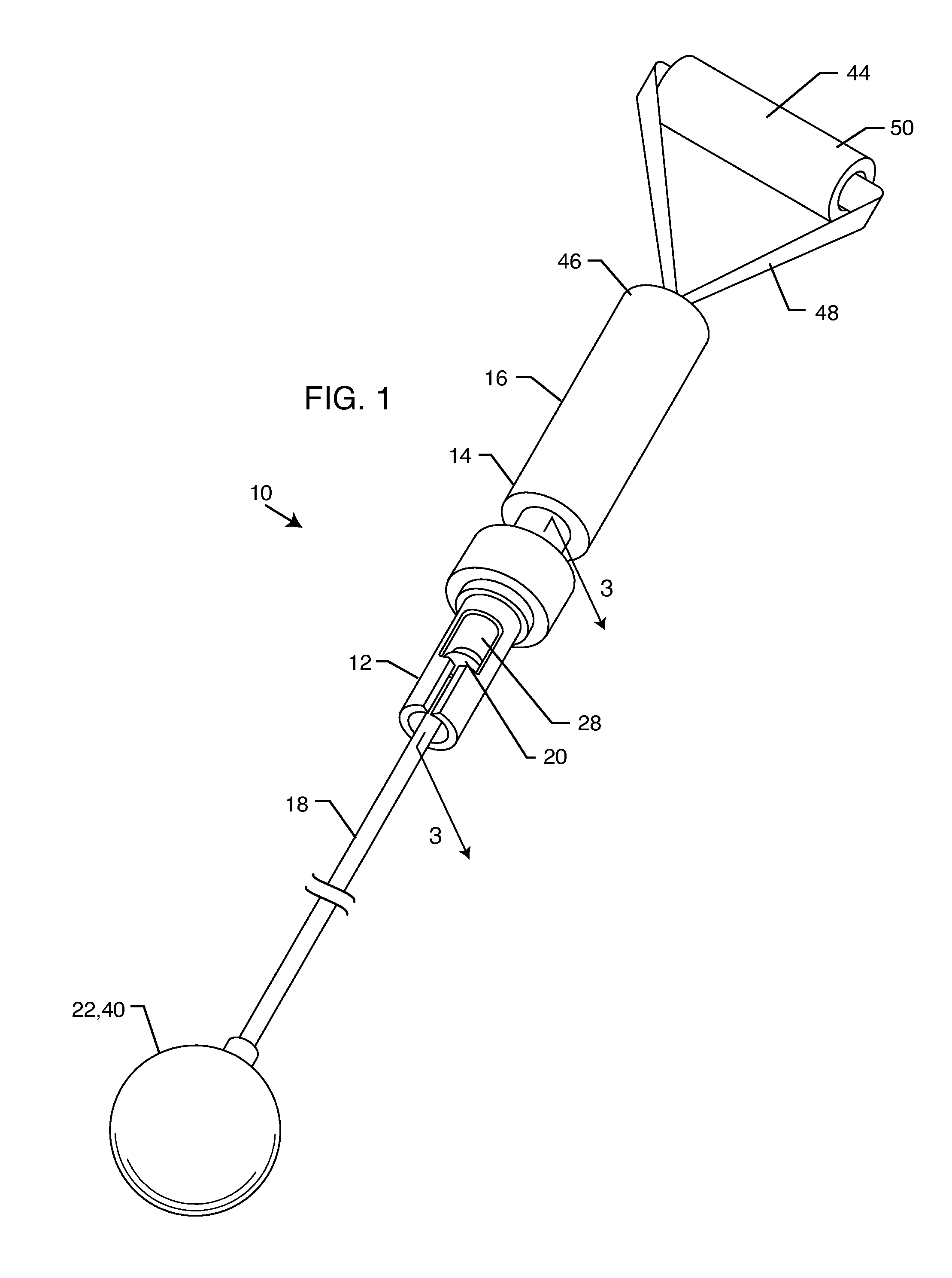
[0028]FIG. 1 is a perspective view of an exercise device 10 embodying the present invention. An exemplary embodiment of the device 10 includes a rope-less jump rope and a resistance exercise device. A person may utilize the device 10 as either the rope-less jump rope or the resistance exercise device.

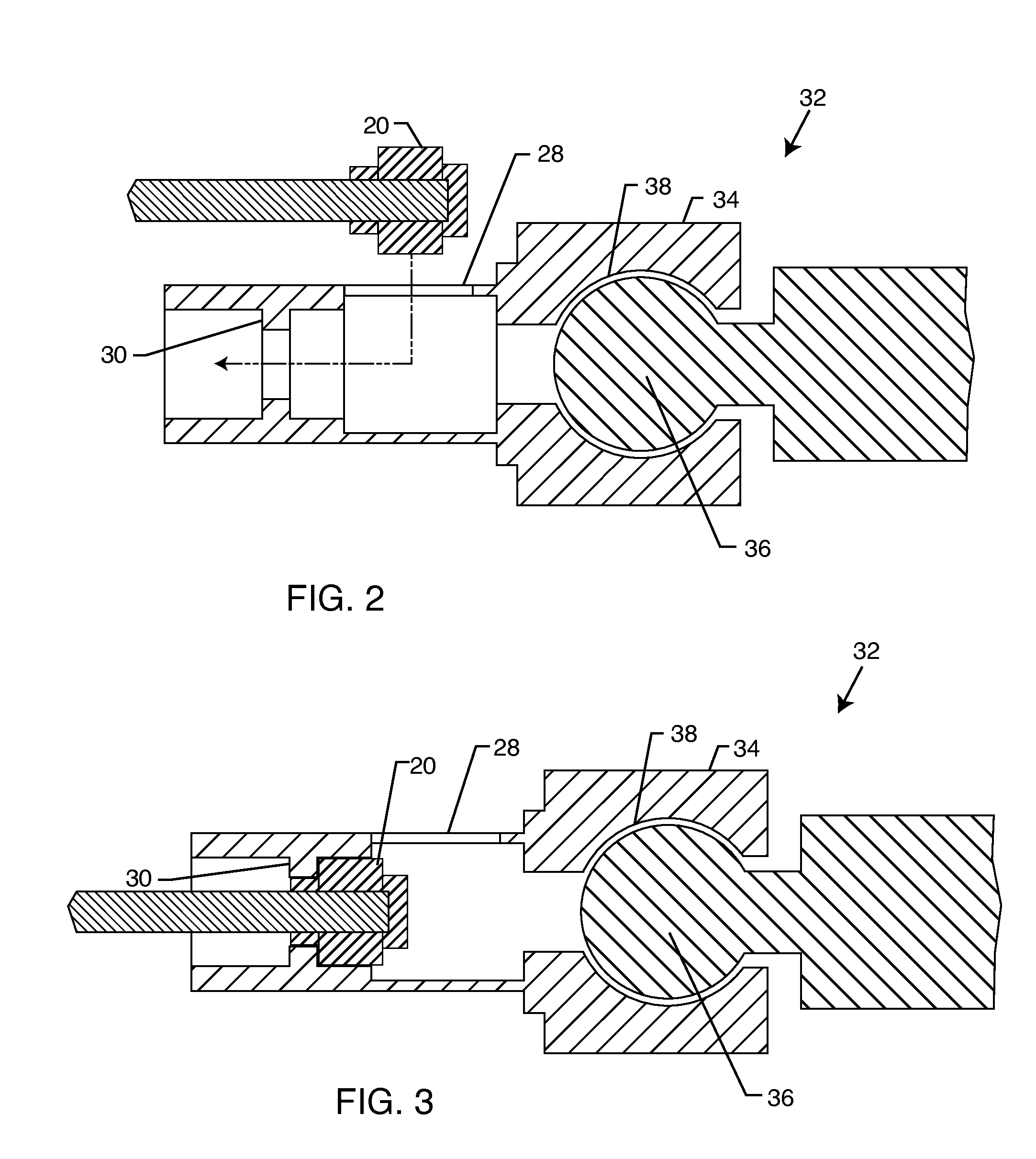
[0029]A receiver 12 is attached relative to an end 14 of a handle 16. An elongated lash 18 includes a connector end 20 and a free end 22. The connector end 20 is removably connectable with the receiver 12, as is shown in FIGS. 2 and 3. The lash 18 comes in various forms including, but not limited to a flexible, resilient hollow tube, a solid extruded material, a solid molded material, a line, a rod, a rope, a cord, a strip, a chain, a braid or the like. The lash 18 made be made of various materials including, but not limited to a natural material, a synthetic material (e.g., PVC, plastic or the like), and combinations thereof. The length and thickness of the lash 18 may vary but the las...


PUM


Abstract

A rope-less jump rope and resistance exercise device includes a jump rope handle having a longitudinal length between a first and second end. A resistance handle is attached to the first end of the jump rope handle disposed substantially perpendicular to the jump rope handle. A single ball-and-socket assembly is attached between the second end of the jump rope handle and a receiver. An elongated lash includes a connector end and a free end, where the connector end is removably connectable with the receiver. The receiver includes a slotted aperture and a stop. An elongated and resiliently stretchable resistance member includes a pair of second connector ends, where either of the pair of second connector ends are removably connectable with the receiver. An identical pair of the jump rope handle, ball-and-socket assembly, receiver, lash and resistance member form the rope-less jump rope and resistance exercise device.

Description

[0001]This disclosure is a continuation-in-part of Ser. No. 11 / 846,307, filed Aug. 28, 2007, now Publication No. 2009 / 0062084. The contents of the previously filed application are incorporated herein in full by this reference.BACKGROUND OF THE INVENTION[0002]The present invention relates to exercise devices. More particularly, the present invention relates to a rope-less jump rope simulator and resistance exercise device.[0003]Generations of young people have enjoyed playing jump rope and many athletes, such as boxers, has used jump ropes for aerobic exercise and physical conditioning. Conventional jump ropes are typically constructed of a pair of handles interconnected by a rope, as seen in U.S. Pat. No. 1,462, 088. The handles of these conventional jump ropes have been constructed of solid wood, plastic or the like with the rope mechanically connected thereto.[0004]However, conventional jump ropes such as those described above, have certain disadvantages. For example, the use of t...

Claims


Application Information

Patent Timeline
Patent Type & Authority Applications(United States)
IPC IPC(8): A63B5/22
CPCA63B5/20
Inventor GAMBOA, RICARDOGARCIA, PETER T.
Owner BORG UNLTD
Why Eureka
Try Eureka