

Golf club shaft
a golf club and shaft technology, applied in the field of golf club shafts, can solve the problems of increasing the number of golf players having troubles on elbows and shoulders, the difficulty of ensuring the safety of the shaft, and the difficulty so as to achieve the effect of maintaining the strength and rigidity of the shaft, reducing the loss, and reducing the loss
- Summary
- Abstract
- Description
- Claims
- Application Information
AI Technical Summary
Benefits of technology
Problems solved by technology
Method used
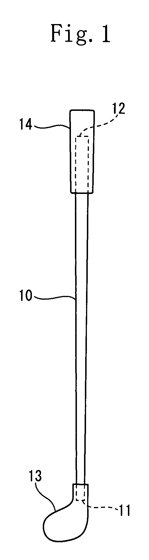
Image

Examples
example 1
[0126]The shaft of the example 1 had the same construction as that of the shaft of the first embodiment.
[0127]More specifically, the second prepreg P2 had a loss factor of 0.3. The second prepreg P2 was disposed in a region of 400 mm from the head-side tip of the shaft. The weight of the second prepreg P2 was set to 1.5 g which was 2% of the first laminate I. The number of layers of the second prepreg P2 was one. The fibrous angle of the reinforcing fiber was set to 90°. The second prepreg P2 was disposed at the tenth layer from the inner peripheral side of the shaft having 21 layers. A second laminate (second prepreg) II was entirely (100%) disposed inside the central region in the thickness direction of the shaft.
[0128]The loss factor of the first laminate I was set to 0.01.
[0129]Each of the fiber reinforced prepregs constructing the shaft is as described below.
[0130]Prepregs produced by Toray Industries Inc. was used to compose each of the first prepregs P1. A prepreg having a ar...
example 2
[0132]The shaft of the example 2 had the same construction as that of the shaft of the second embodiment.
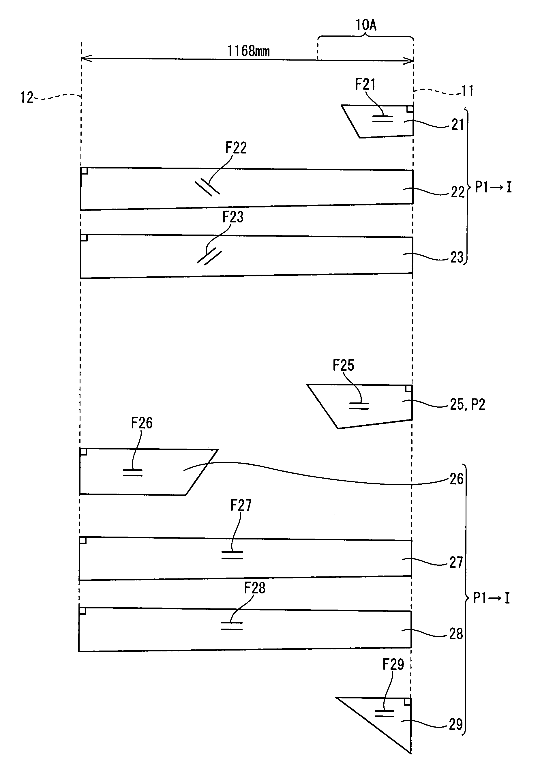
[0133]More specifically, the second prepreg P2 was disposed in a region spaced at an interval of 400 mm to 800 mm from the head-side tip 11. The weight of the second prepreg P2 was 2.0 g which was 3% of the first laminate I. The second prepreg P2 was disposed at the seventh layer from the inner peripheral side of the shaft having 13 layers. The second laminate II was entirely (100%) disposed inside the central region in the thickness direction of the shaft.
[0134]Other constructions and prepreg used were identical to those of the shaft of the example 1. The loss factor of the first laminate I and the second prepreg P2 were set to 0.01 and 0.3 respectively.
example 3
[0135]The shaft of the example 3 had the same construction as that of the shaft of the third embodiment.
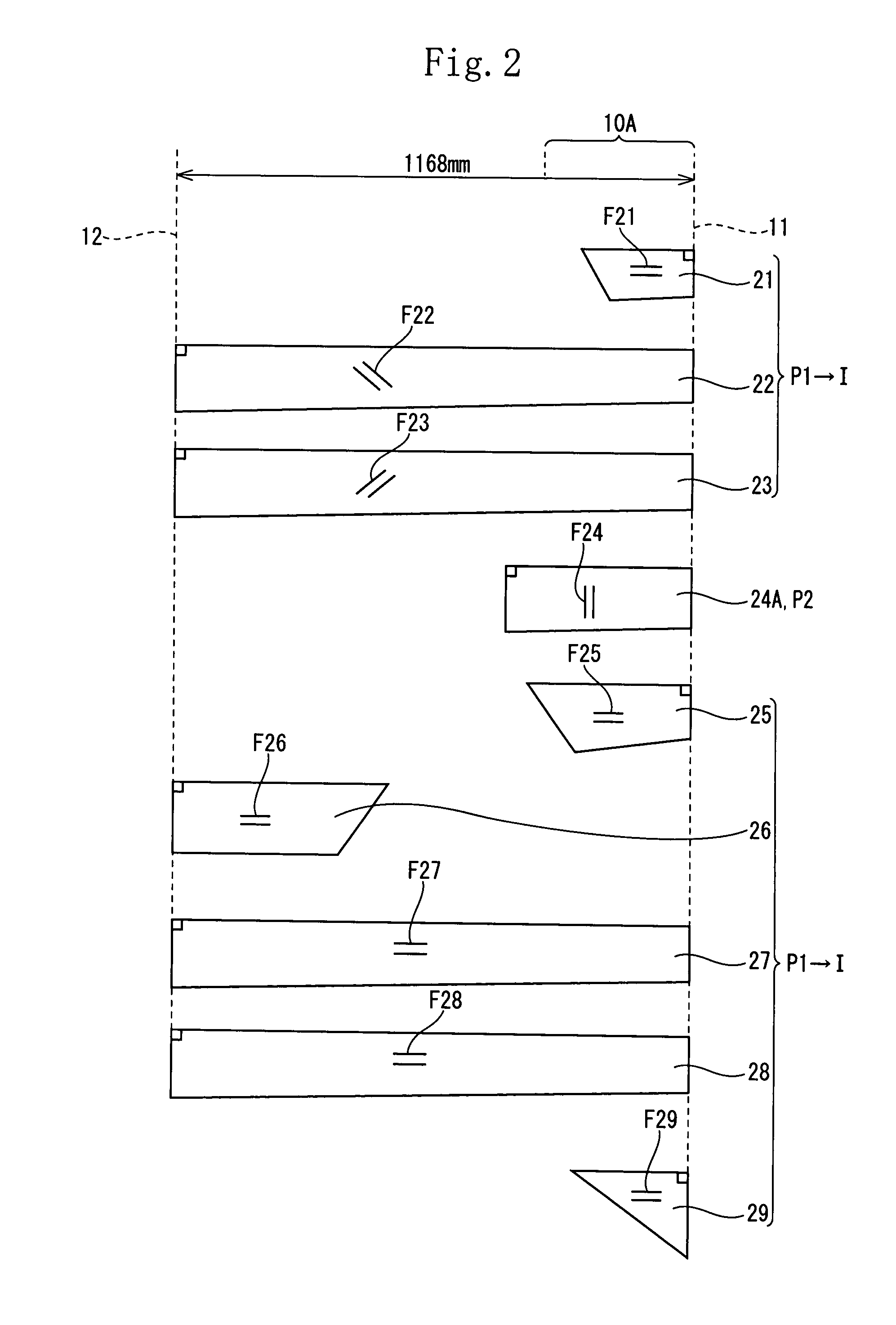
[0136]More specifically, the second prepreg P2 was disposed in a region spaced at an interval of 800 mm to 1168 mm from the head-side tip 11. The weight of the second prepreg P2 was set to 2.5 g which was 4% of the first laminate I. The second prepreg P2 was disposed at the seventh layer from the inner peripheral side of the shaft having 13 layers. The second prepreg P2 was entirely (100%) disposed inside the central region in the thickness direction of the shaft.
[0137]Other constructions and prepregs of the shaft were identical to those of the shaft of the example 1. The loss factor of the first laminate I and that of the second prepreg were set to 0.01 and 0.3 respectively.
PUM
 Abstract
Description
Claims
Application Information