Easily implantable and stable nail-fastener for skeletal fixation and method

a stable and easy-to-implement technology, applied in the field of easy-to-implement and stable nail-fastener for skeletal fixation and method, can solve problems such as independency

Inactive Publication Date: 2011-12-22
KETTERING UNIVERSITY
View PDF2 Cites 11 Cited by
  • Summary
  • Abstract
  • Description
  • Claims
  • Application Information

AI Technical Summary

Benefits of technology

[0005]The invention provides for an intramedullary nail-fastener characterized by a compression transmission device having an interior space being greater than the compression portion diameter of the fastener for providing space at least partially about the fastener for allowing the fastener axis to be variously disposed relative to the interior space.
[0006]The invention also p...

Problems solved by technology

Additionally, there is interdigitation of the male and...

Method used


Image

  • Easily implantable and stable nail-fastener for skeletal fixation and method
  • Easily implantable and stable nail-fastener for skeletal fixation and method
  • Easily implantable and stable nail-fastener for skeletal fixation and method

Examples


Embodiment Construction

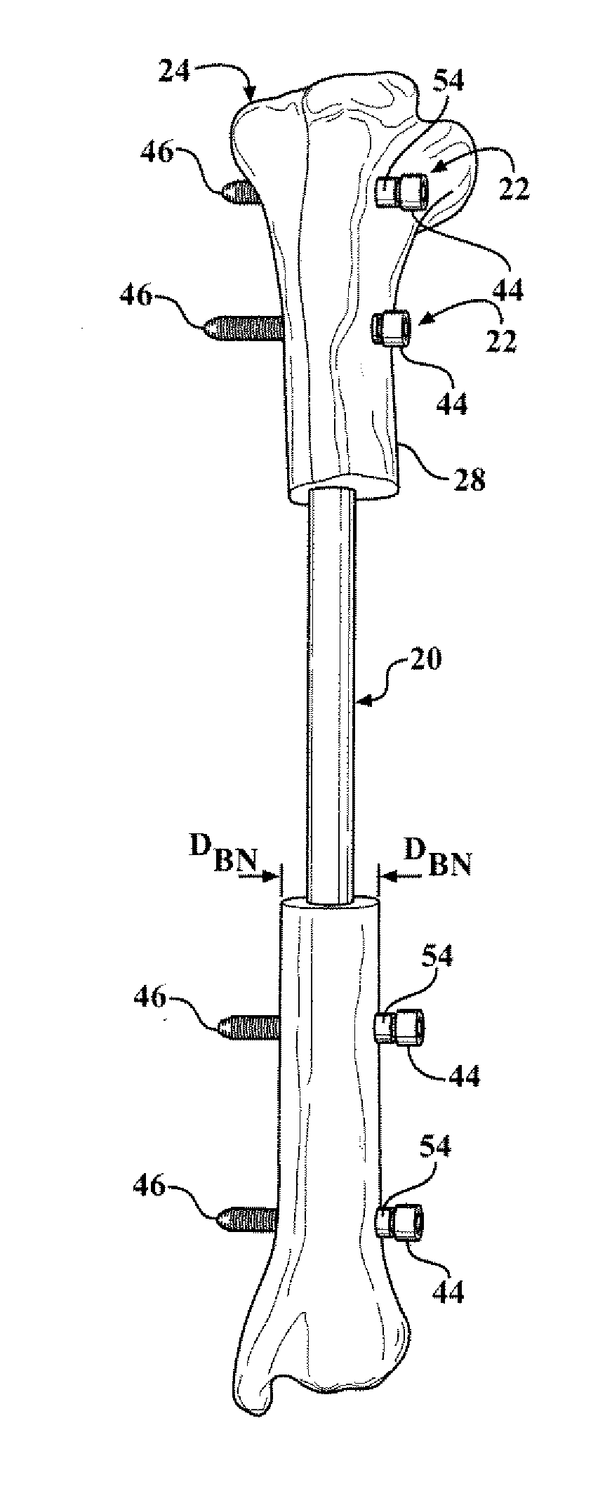
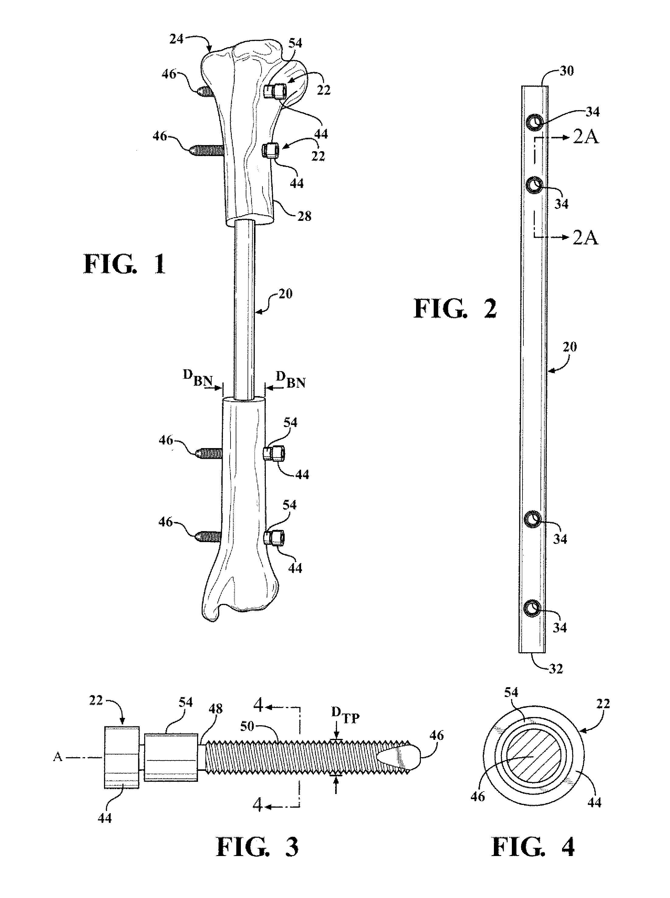
[0028]Referring to the Figures, wherein like numerals indicate corresponding parts throughout the several views, a intramedullary nail 20 and fasteners 22 for skeletal fixation constructed in accordance with the subject invention is shown in FIGS. 1-14.

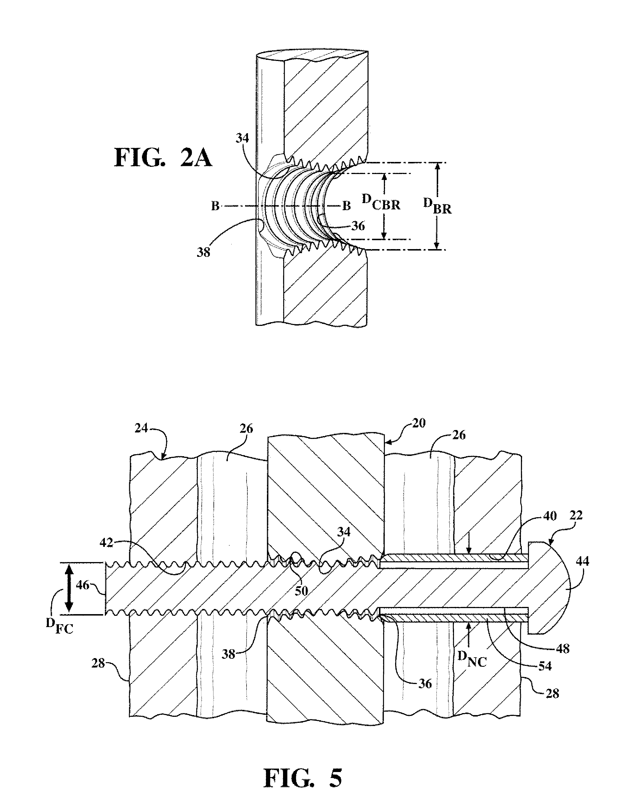
[0029]The nail-fastener construct includes an intramedullary nail 20 for insertion into a bone 24 having a bone diameter DBN and including a medullary canal 26 surrounded by a cortex 28. The intramedullary nail 20, generally indicated, extends longitudinally in the medullary canal 26 of the bone 24 between a top end 30 and a bottom end 32 thereof and defines a bore 34 disposed transverse to, i.e., extending across but is not necessarily perpendicular to, the intramedullary nail 20. The intramedullary nail 20 may be straight, have an acute sharp bend, be bowed, or spiraled. The bore 34 is threaded and has a bore axis B extending between the near opening 36 and the far opening 38 transverse to the intramedullary nail 20. The bore 34 has...


PUM


Abstract

An intramedullary nail (20) for insertion into the medullary canal (26) in a bone (24) surrounded by the cortex (28) and defines a bore (34) extending transverse to the intramedullary nail (20). A threaded fastener (22) extends along a fastener axis (A) and has a compression portion (48) having a compression portion diameter (DCP), and a threaded portion (50) having a threaded portion diameter (DTP) extending through a near cortex hole (40) and a far cortex hole (42), both holes (40, 42) radially overlapping the bore (34) and the threaded portion diameter (DTP) threadedly engaging the bore (34). A compression transmission device (54) has an exterior (56) and an interior (58) and defines an interior space for transmitting the compressional load of the threaded fastener (22) to the intramedullary nail (20). The threaded fastener (22) extends through the compression transmission device (54) and the intramedullary nail (20) and the far cortex hole (42) for threadedly engaging the bore (34) and fixating the intramedullary nail (20) within the medullary canal (26). The interior space of the compression transmission device (54) is greater than the compression portion diameter (DCP) of the fastener (22) for providing space at least partially about the threaded fastener (22) for allowing the fastener axis (A) to be variously disposed relative to the interior space.

Description

BACKGROUND OF THE INVENTION[0001]1. Field of the Invention[0002]An easily implantable and stable nail-fastener for skeletal fixation to treat bone fractures and to provide support to the long bones and a method for implanting the nail-fastener.[0003]2. Description of the Prior Art[0004]An intramedullary nail for skeletal fixation of the type to which the subject invention pertains includes a threaded fastener extending through a compression transmission device to threadedly engage the nail. The compression transmission device transmits the compressional load of the threaded fastener to the intramedullary nail during fixation. One such nail-fastener device is illustrated in U.S. Patent Application No. 2009 / 0326533 to Dell'Oca, which discloses a two-diameter, two-piece locking bolt. The smaller diameter portion or male part of the bolt screws into the larger diameter portion or female part of the bole and threadedly engages the nail. The female part of the two diameter locking bolt ab...

Claims


Application Information

Patent Timeline
IPC IPC(8): A61B17/58
CPCA61B17/7241A61B17/7233
Inventor LECRONIER, DAVIDATKINSON, PATRICK
Owner KETTERING UNIVERSITY
Why Eureka
Try Eureka