
Multi-sense environmental monitoring device and method

a monitoring device and environmental technology, applied in the field of environmental monitoring devices, can solve the problems of insufficient calibration policy, serious threat to worker safety, and workers at risk of being exposed to a variety of hazardous environmental substances, and achieve the effect of meeting the more stringent emerging tlv requirements and ensuring the accuracy level

Active Publication Date: 2011-12-29
INDUSTRIAL SCIENTIFIC CORPORATION
View PDF17 Cites 30 Cited by
  • Summary
  • Abstract
  • Description
  • Claims
  • Application Information

AI Technical Summary

Benefits of technology

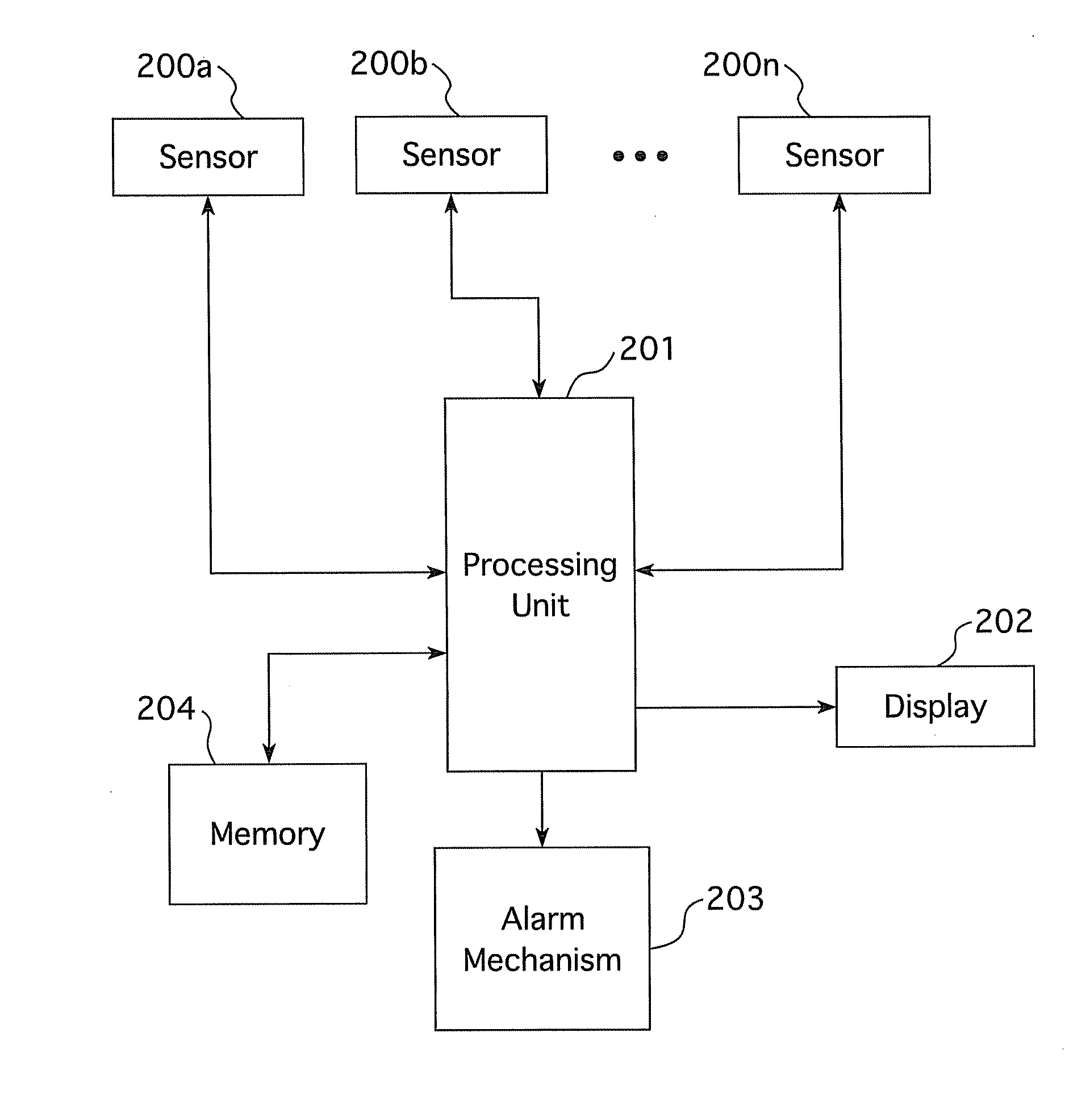
[0012]In one general aspect, embodiments of the present invention generally pertain to a monitoring device having at least two sensors for each substance to be detected, a display, a processing unit, and an alarm. The sensors may be positioned on more than one plane or surface of the device. The

Problems solved by technology

In a number of industrial work environments workers are at risk of being exposed to a variety of hazardous environmental substances such as toxic or highly combustible gases, oxygen depleted environments, or radiation, etc. that pose a serious threat to worker safety.
While a number of manufacturers sell automated docking stations that automatically perform calibration and bump testing when a monitoring device is docked, there are still a number of disadvantages to the current practice.
Such a fixed policy (bump test every day and calibrate every thirty days) by its very nature is a compromise that is too stringent in many cases and too liberal in many others.
Current practice of a fixed calibration policy, such as calibrate every thirty days, may not be enough to guarantee the level of accuracy to meet the more stringent emerging TLV's.
While a blanket reduction in the frequency of the calibration interval, i.e. from thirty days, will help to improve accuracy, it would add significant cost to the use and maintenance of the environmental monitoring devices.
While there certainly is value in this approach, the cost of these emerging sensor often preclude its widespread use, particularly in personal monitoring applications where a large number of these monitors need to be deployed.

Method used


Image

  • Multi-sense environmental monitoring device and method
  • Multi-sense environmental monitoring device and method
  • Multi-sense environmental monitoring device and method

Examples


example

[0032]The following discussion illustrates a non-limiting example of embodiments of the present invention.

[0033]A single gas monitor that is used as a small portable device worn on the person and used primarily as personal protection equipment may be used to detect the gases within the breathing zone of the bearer of the device. The gas monitor is designed to monitor one of the following gases:

GasSymbolRangeIncrementsMeasuringCarbon MonoxideCO0-1,500  1 ppmRanges:Hydrogen SulfideH2S0-500 ppm0.1 ppmOxygenO20-30% of volume0.1%Nitrogen DioxideNO20-150 ppm0.1 ppmSulfur DioxideSO20-150 ppm0.1 ppm

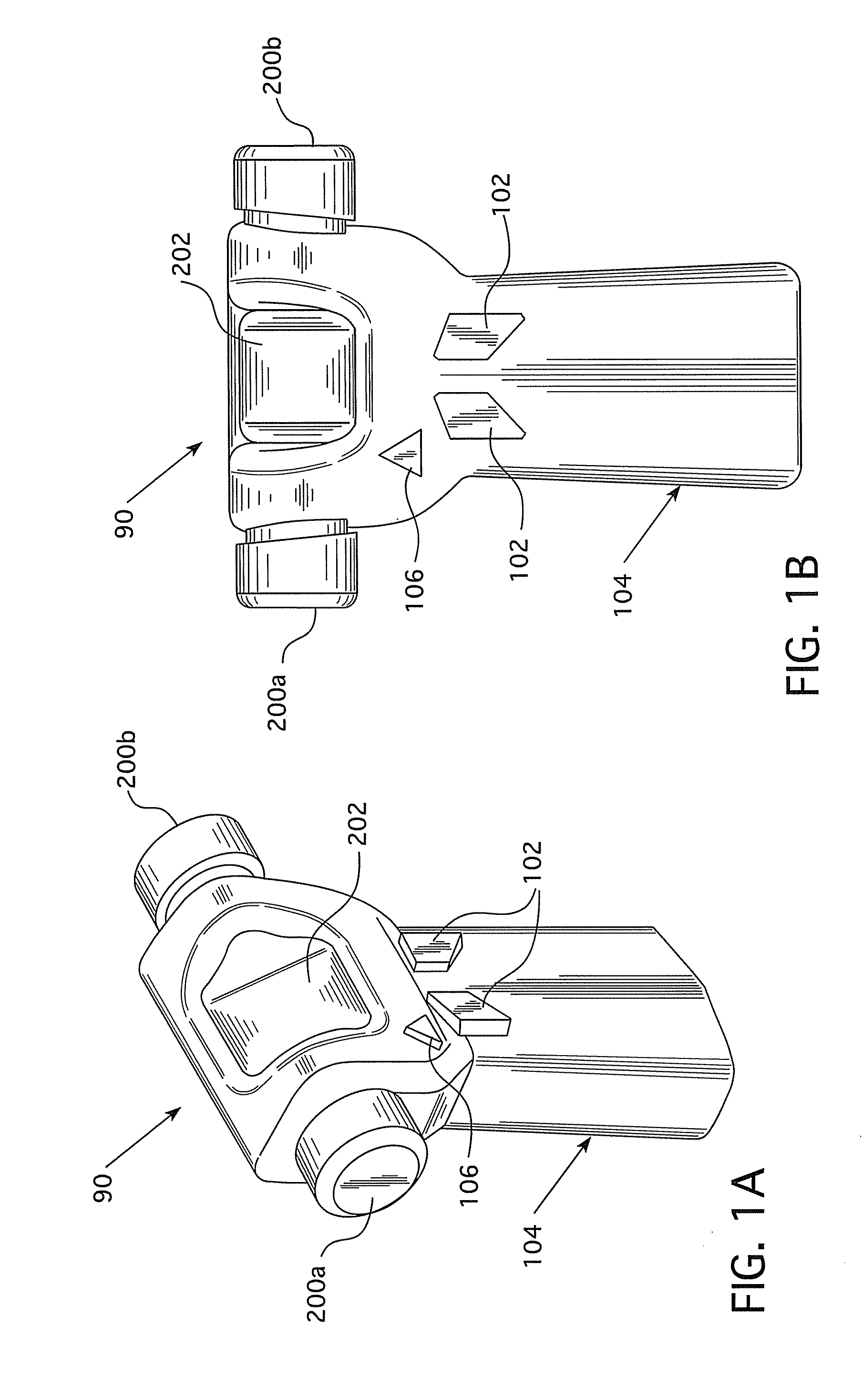
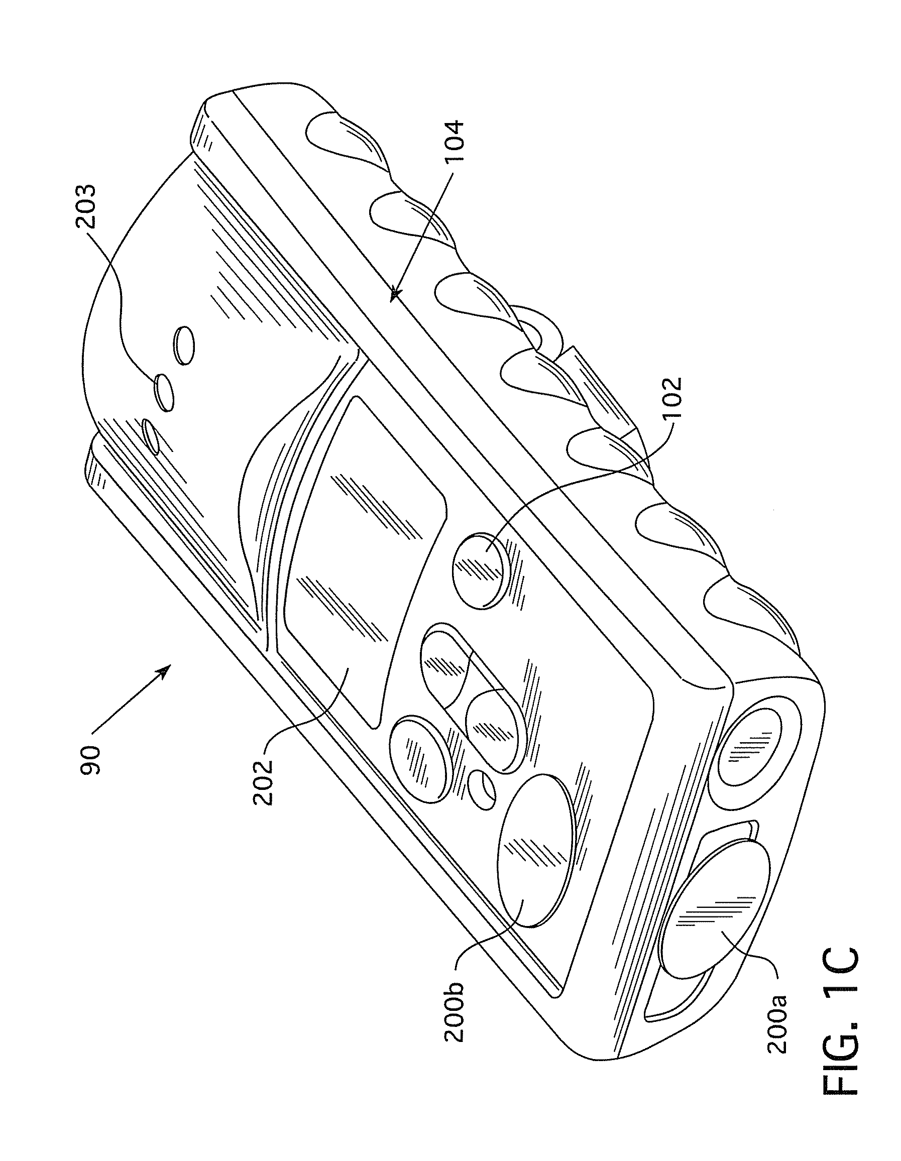
[0034]The sensors are placed on two separate planes of the monitoring device, for example as depicted in FIGS. 1A-C. The gas concentration of the reading is calculated in the following manner:

reading=SensorReading15+SensorReading252

[0035]If the reading is higher (or lower in the case of oxygen) than a user defined alarm threshold, then an audio and visual alarm is generated.

[0036]Further, if read...


PUM


Abstract

An environmental monitoring device for detecting and warning users of unhealthy levels of a given substance is disclosed having more than one sensor for each substance to be detected. Each sensor for each substance detected may be positioned in more than one plane or surface on the device. The device may be capable of auto or self calibration. Methods for reading substance levels and auto calibrating are also disclosed.

Description

CROSS-REFERENCE TO RELATED APPLICATION[0001]The present application claims priority to U.S. Provisional Patent Application No. 61 / 358,729 filed Jun. 25, 2010.FIELD OF THE INVENTION[0002]Embodiments of the present invention generally relate to environmental monitoring devices.BACKGROUND OF THE INVENTION[0003]In a number of industrial work environments workers are at risk of being exposed to a variety of hazardous environmental substances such as toxic or highly combustible gases, oxygen depleted environments, or radiation, etc. that pose a serious threat to worker safety. In order to keep workers safe, specialized environmental monitoring devices are used to alert workers of dangerous changes in their immediate environment.[0004]Current practice involves using fixed point monitoring devices that monitor the environment around where they are deployed or portable monitoring devices that are carried by the workers to monitor their immediate vicinity. Fixed point monitoring devices are t...

Claims


Application Information

Patent Timeline
IPC IPC(8): G08B21/00
CPCG08B21/14G08B21/16G01N33/0063G08B29/24G01N33/0006G08B29/16G01N33/0031G08B5/22G08B21/182G08B29/26
Inventor ARUNACHALAM, RAGHU
Owner INDUSTRIAL SCIENTIFIC CORPORATION
Learn More