Eureka AIR delivers breakthrough ideas for toughest innovation challenges, trusted by R&D personnel around the world.

Developer Conveying Device and Development Device, Toner Cartridge, and Cleaning Unit that are Provided with Developer Conveying Device

Inactive Publication Date: 2011-12-29
SHARP KK
View PDF7 Cites 16 Cited by
  • Summary
  • Abstract
  • Description
  • Claims
  • Application Information

AI Technical Summary

Benefits of technology

[0021]According to the developer conveying device of the present invention, because the spiral blade of the screw-shaped shaft includes the agitating blade portion whose lead angle increases gradually toward the downstream side at one end on the downstream side in the conveyance direction, an agitating force in a circumferential direction of the rotating shaft is enhanced while conveyance capability of the agitating blade portion in a developer conveyance direction decreases gradually. Because the rotating shaft of the screw-shaped shaft includes the conical portion that thickens gradually toward the downstream side at one end on the downstream side in the developer conveyance direction, the developer is moved in the radial direction of the rotating shaft by the conical portion.
[0022]The developer can quickly move from the developer conveyance path to the downstream opening by a synergistic effect. Therefore, the conditions that the developer is retained by striking on the downstream wall surface of the developer conveyance path and that the retained developer is pressed to receive the stress by the sequentially-conveyed developer can be suppressed. As a result, the problem, in which the toner fluidity improver (additive) is buried in the resin particles constituting the toners by the heat generation or the shear force due to the stress and therefore the developer fluidity is extremely degraded to degrade the toner fluidity, can be solved.
[0023]According to the development device including the developer conveying device and the image forming apparatus, the degradation of the developer fluidity can be suppressed to suppress the degradation of the print image density. According to the toner cartridge including the developer conveying device and the image forming apparatus, the lock phenomenon of the screw-shaped shaft is prevented, so that the toner can stably be supplied to the development device to form the image on the recording sheet at the stable image density. According to the cleaning unit including the developer conveying device and the image forming apparatus, the lock phenomenon of the screw-shaped shaft is prevented, so that an accident that the removed toner (waste toner) overflows onto the photoconductor drum side to contaminate the inside of the image forming apparatus with the toner because the cleaning unit is filled with the removed toner can be prevented to maintain a cleaning function of the cleaning unit.

Problems solved by technology

A toner fluidity improver (additive) is buried in resin particles constituting the toners by the heat generation or the shear force due to the stress, and the developer fluidity is extremely degraded to hardly supply the sufficient amount of toner to the photoconductor drum through the development roller, which results in a problem in that density of an image printed on a recording medium is degraded.
Therefore, the problem in that the density of the print image is degraded due to the degradation of the developer fluidity is not solved yet.
There is also the problem similar to that of the development device in the toner cartridge of Japanese Patent Application Laid-Open No. 2006-235255 that replenishes the unused toner to the development device and a conventional cleaning unit that removes the toner left on the photoconductor drum or a transfer belt after the toner image is transferred to a recording sheet.
That is, for the conventional toner cartridge or cleaning unit, when the auger screw is rotated to convey the toner to a toner discharge port that is disposed on the downstream side of the toner conveyance path, the toner adheres to and deposits on a downstream wall surface of the toner conveyance path, and unfortunately the deposited toner receives a pressure from the sequentially-conveyed toner to be retained on the downstream wall surface.
Additionally, the toner retained on the downstream wall surface of the toner conveyance path becomes a consolidation state to lead to a lock phenomenon that obstructs the rotation of the auger screw.

Method used


Image

  • Developer Conveying  Device and Development Device, Toner Cartridge, and Cleaning Unit that are Provided with Developer Conveying Device
  • Developer Conveying  Device and Development Device, Toner Cartridge, and Cleaning Unit that are Provided with Developer Conveying Device
  • Developer Conveying  Device and Development Device, Toner Cartridge, and Cleaning Unit that are Provided with Developer Conveying Device

Examples


fifth embodiment

(Cleaning Unit of Fifth Embodiment)

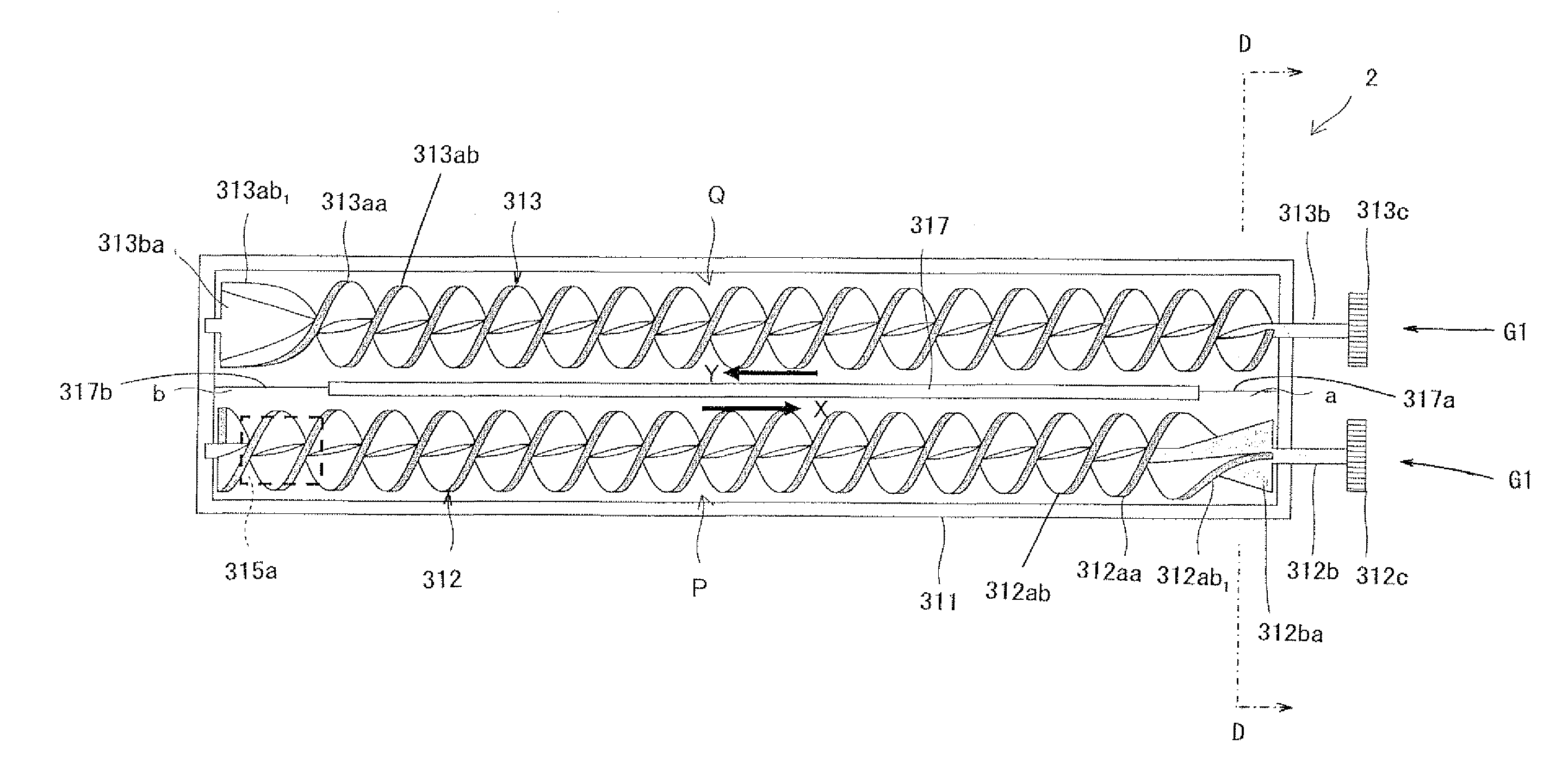
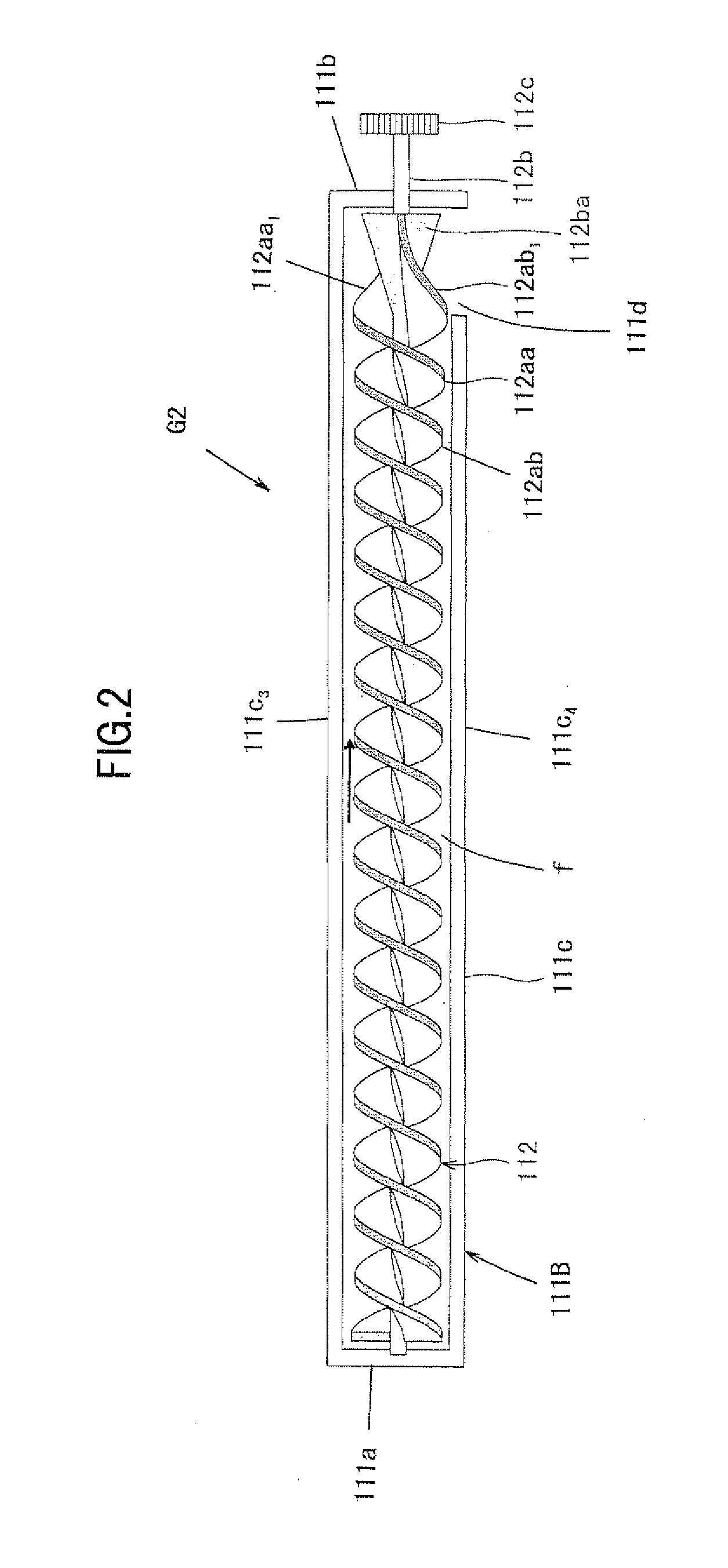
[0119]FIG. 17 is a schematic sectional view illustrating a configuration of a cleaning unit according to a fifth embodiment of the present invention mounted on the image forming apparatus of the third embodiment when being viewed from an upstream side, and FIG. 18 is a sectional view illustrating the cleaning unit of the fifth embodiment. More particularly, the cleaner unit 4 or the intermediate transfer belt cleaning unit 9 (see FIG. 8) of the image forming apparatus of the third embodiment is replaced with a cleaning unit 500 of FIGS. 17 and 18. The cleaning unit 500 includes the developer conveying device G2 (see FIG. 2), an upper blade member (cleaning blade) 502, and a lower blade member (waste toner anti-drop mylar) 503. The upper blade member (cleaning blade) 502 and the lower blade member (waste toner anti-drop mylar) 503 are mounted at opening edges of a toner introduction port 501 a in the developer conveying cylinder 511 of the developer...


PUM


Abstract

A developer conveying device comprising: a developer conveying cylinder; and a screw-shaped shaft, wherein the screw-shaped shaft includes a rotating shaft that is journaled in an upstream wall portion and a downstream wall portion, which are included in the developer conveying cylinder, and a spiral blade that is mounted on an outer circumferential surface of the rotating shaft; the rotating shaft includes a conical portion that thickens gradually toward the downstream side; and the spiral blade includes an agitating blade portion whose lead angle increases gradually toward the downstream side.

Description

CROSS-REFERENCE TO RELATED APPLICATION[0001]This application is related to Japanese patent application No. 2010-142826 filed on Jun. 23, 2010 whose priority is claimed under 35 USC §119, the disclosure of which is incorporated by reference in its entirety.BACKGROUND OF THE INVENTION[0002]1. Field of the Invention[0003]The present invention relates to a developer conveying device that conveys a developer containing at least a toner, and a development device, a toner cartridge, and a cleaning unit which are provided with the developer conveying device.[0004]2. Description of the Related Art[0005]Recently a two-component developer (hereinafter simply referred to as “developer”) having excellent toner charging stability is widely used in an electrophotographic image forming apparatus that meets a full-color image and a high-quality image. The developer includes a toner and a carrier. When the developer is agitated in a developer tank of a development device, a properly-charged toner is ...

Claims


Application Information

Patent Timeline
IPC IPC(8): G03G15/08G03G21/00
CPCG03G15/0822G03G2215/0838G03G2215/0833G03G2215/0822
Inventor HAYASHI, SHIGEKINAGAI, TAKAFUMI
Owner SHARP KK
Why Eureka
Eureka Blog
Learn More