Eureka AIR delivers breakthrough ideas for toughest innovation challenges, trusted by R&D personnel around the world.

Rotatable wedge valve mechanism and method for manufacture

Inactive Publication Date: 2008-04-24
CHROMATIC IND LLC
View PDF22 Cites 19 Cited by
  • Summary
  • Abstract
  • Description
  • Claims
  • Application Information

AI Technical Summary

Benefits of technology

[0013]It is a principal feature of the present invention to provide a novel rotatable wedge valve mechanism having a rotatable wedge member that defines a pair of spaced relatively thick wall sections, which may be of differing thickness and having a relatively thin wall section between the relatively thick wall sections. The wall thickness of the rotatable wedge valve member achieves a wedging or camming activity with surfaces of increasing thickness from the thin wall section to the thicker wall sections, depending on the direction of rotational movement, applying mechanically enhanced force to seat members as the rotatable wedge member approaches its open or closed positions.
[0015]It is a feature of the present invention to provide a novel method for manufacturing a rotatable wedge valve member which permits the development of regions of valve wall thickness that are of greater thickness as compared with other regions and where in thicker regions of wall thickness may be tuned according to the intended service of the valve or the needs of a customer.
[0016]It is another feature of the present invention to provide a novel cartridge type rotatable wedge valve mechanism incorporating mechanical features that are applicable to more conventional valve designs and which are applicable to cartridge valve designs permitting simple and efficient replacement of a rotatable wedge valve cartridge within a valve body that remains connected within a flowline.
[0017]It is also a feature of the present invention to provide a novel rotatable wedge valve mechanism having a rotatable wedge valve member having a curved valve section defining a flow port and having a non-uniform wall thickness that defines an outer convex wall surface that causes increase and decrease of force on a valve seat member for enhanced control of forces at predetermined positions of the valve member.
[0019]Briefly, the various objects and features of the present invention are realized through the provision of a rotatable wedge valve mechanism having improvements as compared with the valve mechanisms that are set forth in U.S. Pat. Nos. 4,962,911, 5,333,834 and 5,507,469 of Soderberg. Within a valve chamber of a valve body a core member is maintained in substantially immoveable position by a mechanical support system which can conveniently take the form of a seat assembly and a spacer member. If desired, the core member and the spacer member may be a single integral component. The core member defines an external spherical surface or spherical surface segments and is engaged by a corresponding concave spherical surface portion of a rotatable wedge valve member that is rotatable within the valve chamber and relative to the core member between open and closed positions. The rotatable wedge valve member may be of the floating variety or it may be supported for rotation within a valve body by a stem and trunnion arrangement. The stem and trunnion may be separate components having appropriate driving and supporting relation with the rotatable wedge valve member or may be integral components of the valve member for simplicity and efficiency of manufacture and assembly.

Problems solved by technology

However, these valves offer only minimal graduated control of fluid flow by setting the plug cock at intermediate positions and require modification for use in high pressure environments.
The valves described above fail to provide a valve operable between fully opened and fully closed positions in a quarter of one rotation or less while providing improved sealing in high pressure applications and shielding of the seat surface from erosion by the flowing fluid in both the opened and closed positions.
It is well known that valves often become unserviceable and need repair or replacement.

Method used


Image

  • Rotatable wedge valve mechanism and method for manufacture
  • Rotatable wedge valve mechanism and method for manufacture
  • Rotatable wedge valve mechanism and method for manufacture

Examples


Embodiment Construction

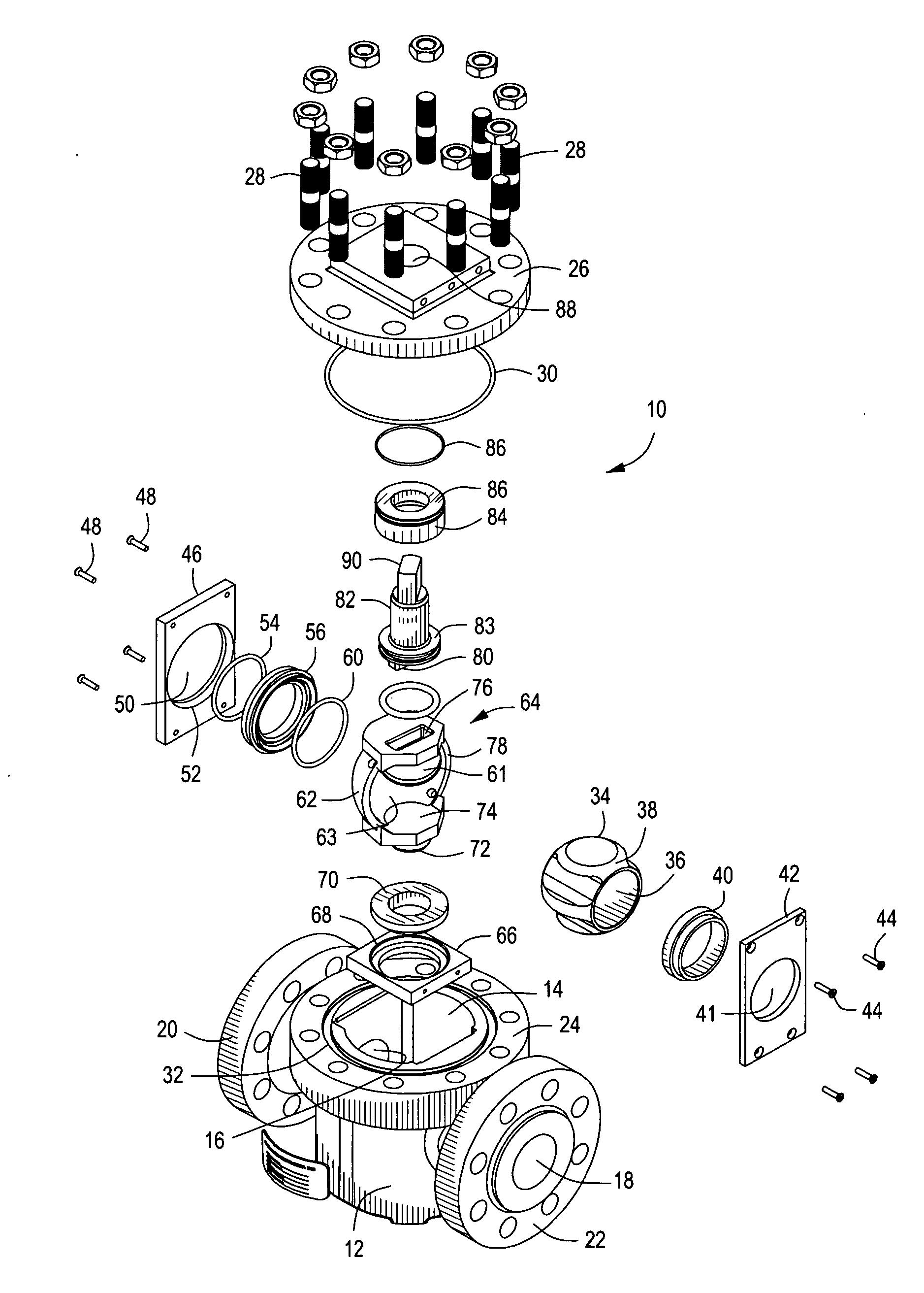
[0032]Referring now to the drawings and first to FIG. 1, a rotatable wedge valve mechanism is shown generally at 10 and embodies the principles of the present invention. FIG. 1 is an exploded isometric illustration showing the various components of the valve mechanism and their relationships. The valve mechanism 10 has a valve body or housing 12 defining an internal valve chamber 14 and having fluid flow passages 16 and 18 in communication with the valve chamber. The valve body is provided with connection members 20 and 22 enabling connection of the valve body to a flow line, not shown. The connection members are shown in FIG. 1 to be in the form of connection flanges that receive bolts or threaded studs that establish bolted mounting of the valve mechanism in a flow line having corresponding connection flanges. A variety of other flow line connection systems are commercially available and may be used for valve / flow line connection without departing from the spirit and scope of the ...


PUM


Abstract

A rotatable wedge valve mechanism has a valve body or valve cartridge defining a valve chamber and flow ports in fluid communication with the valve chamber. A valve seat is located within the valve chamber in registry with one of the flow ports. A non-rotatable core member having a convex external surface portion is supported within said valve chamber. A wedge member is mounted for rotation within the valve chamber and has a range of rotary motion between open and closed positions of said valve and a non-uniform wall thickness throughout said range of rotary motion. An actuator upon rotary movement achieves opening and closing rotation of said wedge member. A method is provided for machining concave and convex wedge member surfaces from selected center-points to achieve relative thicknesses of wall sections of the wedge member.

Description

RELATED PATENTS[0001]The present invention is generally related to the subject matter of U.S. Pat. Nos. 4,962,911, 5,333,834 and 5,507,469, each issued to Paul B. Soderberg and each being commonly owned with respect to the subject matter hereof.BACKGROUND OF THE INVENTION[0002]1. Field of the Invention[0003]The present invention relates generally to rotatable wedge valves that constitute improvements over the teachings of the Soderberg patents identified above. More specifically, the present invention concerns rotatable wedge valves having a rotatably actuated wedge member that has a geometry permitting force induced sealing with respect to seat members at both the open and closed positions of the rotatable wedge member. Even more specifically, the present invention is directed to a rotatable wedge valve mechanism that can be efficiently employed in replaceable cartridge valves as well as valves that must be assembled to or removed from a flow conduit as a valve unit.[0004]2. Descri...

Claims


Application Information

Patent Timeline
IPC IPC(8): F16K5/06
CPCF16K5/0605F16K5/204F16K5/0621Y10T137/0508Y10T137/6031
Inventor CHURCH, KRIS L.
Owner CHROMATIC IND LLC
Why Eureka
Eureka Blog
Learn More