Renewable Energy System

a renewable energy and energy system technology, applied in water-power plants, machines/engines, electric generator control, etc., can solve the problems of short-sightedness in ignoring water as a source of renewable energy, insufficient storage systems to meet the ever increasing needs of the world's population, and energy shortages are now commonplace, so as to dampen wave action

Inactive Publication Date: 2012-01-26
EKERN ROD
View PDF32 Cites 38 Cited by
  • Summary
  • Abstract
  • Description
  • Claims
  • Application Information

AI Technical Summary

Benefits of technology

[0018]In one preferred form, the water wheel is mounted on a floating weir, the weir being located in a water channel with the weir supporting the water wheel at a selected constant depth in the channel as the tide level increases or decreases in height. The water wheel assembly may be located in a lagoon with a suitably arranged barricade being positioned at a mouth location of the water channel to dampen wave action in the lagoon which could impact the water wheel assembly.

Problems solved by technology

Despite the current movement supporting renewable energy sources, many legislators and policy-makers are attempting to meet these demands through projects which relate solely to wind and solar power generation, and do not address renewable energy produced from water.
This lack of attention to water as a source of renewable energy is short-sighted.
However, these storage systems are not sufficient to meet the ever increasing needs of the world's population.
As a result, renewable water and energy shortages are now commonplace, and plans for future needs are problematic.
However, this project involves the use of a traditional hydroelectric facility which would not be economically feasible for many underdeveloped parts of the world.

Method used


Image

  • Renewable Energy System
  • Renewable Energy System
  • Renewable Energy System

Examples


Embodiment Construction

[0027]The preferred version of the invention presented in the following written description and the various features and advantageous details thereof are explained more fully with reference to the non-limiting examples included in the accompanying drawings and as detailed in the description which follows. Descriptions of well-known components and processes and manufacturing techniques are omitted so as to not unnecessarily obscure the principle features of the invention as described herein. The examples used in the description which follows are intended merely to facilitate an understanding of ways in which the invention may be practiced and to further enable those skilled in the art to practice the invention. Accordingly, the examples should not be construed as limiting the scope of the claimed invention.

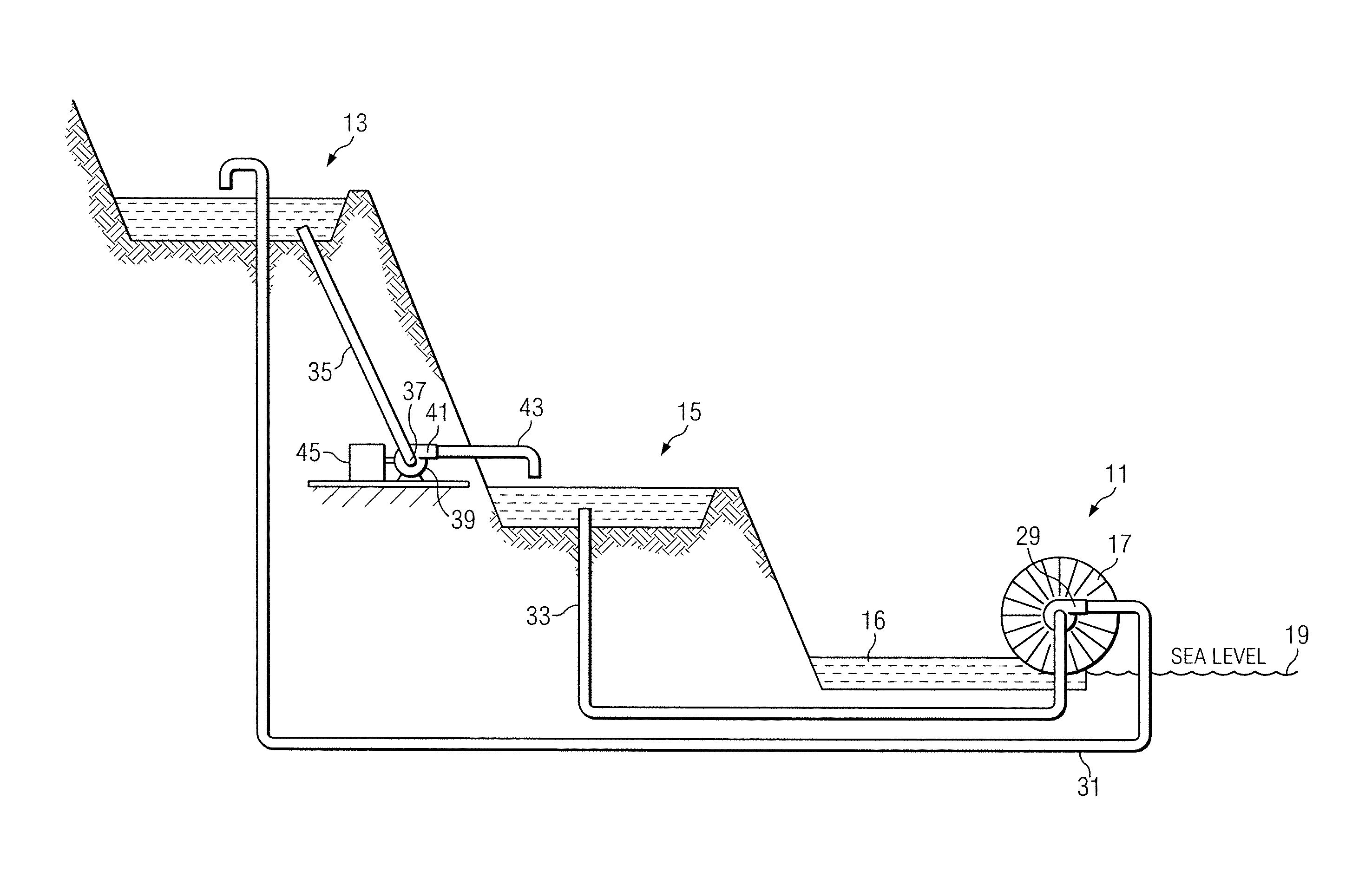
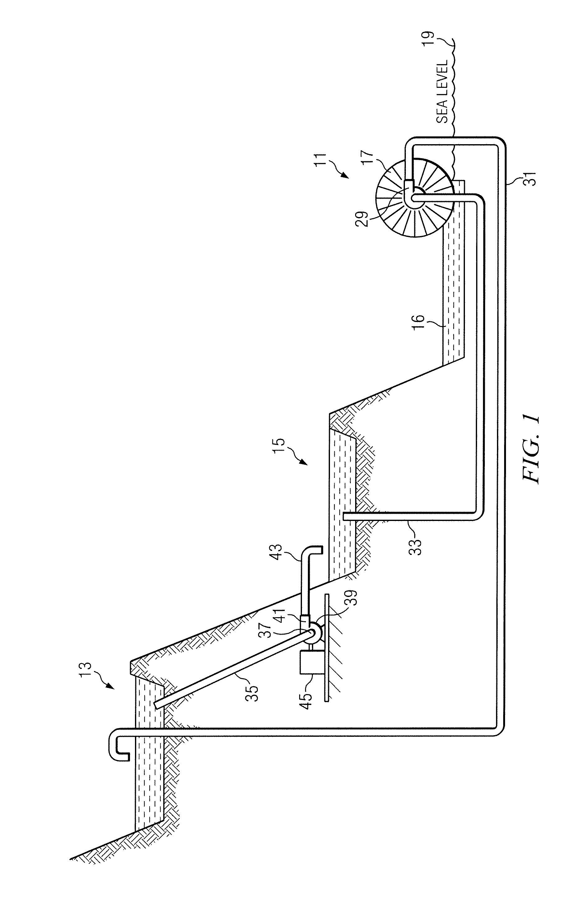
[0028]Turning now to FIG. 1 of the drawings, there is shown a simplified piping schematic of the renewable energy generation system of the invention. As will be described in greate...


PUM


Abstract

A water based renewable energy system is shown which uses tidal flow and an associated water wheel / weir assembly to provide pumping power for the system. A water wheel powered pump and associated piping are used to raise water from a lower lake reservoir to a higher storage lake reservoir. The water which is pumped to the higher storage lake can be released to a generator located at a lower elevation and then returned to the lower storage lake. The cycle can then be repeated by again pumping water from the lower lake to the upper lake. The pumped storage provides flow and head to generate electric power through the turbine generator.

Description

CROSS REFERENCE TO RELATED APPLICATIONS[0001]The present application claims priority from a previously filed provisional application Ser. No. 61 / 365,938, filed Jul. 20, 2010, entitled “Renewable Energy Project”, by the same inventor.BACKGROUND OF THE INVENTION[0002]1. Field of the Invention[0003]The present invention relates generally to sources of renewable energy, and more particularly to a system for harnessing tidal energy, for example to generate electricity or other forms of energy, whether directly or indirectly.[0004]2. Description of the Prior Art[0005]Due to the limitations of non-renewable energy sources, such as oil and coal, as well as the negative environmental effects of such energy sources, a need exists for the provision of alternative energy conversion and transfer systems that are based on renewable sources of power. At the present time, there is increasing interest in renewable energy sources such as solar, wind, wave and tidal power.[0006]The tremendous growth i...

Claims


Application Information

Patent Timeline
Patent Type & Authority Applications(United States)
IPC IPC(8): F03B13/26
CPCF03B13/06F03B13/264Y02E60/17F05B2240/13Y02E10/28F03B17/063E02B9/08Y02E60/16Y02E10/30Y02E10/20
Inventor EKERN, ROD
Owner EKERN ROD
Why Eureka
Try Eureka