
Fabric Dyeing Apparatus and Method

a fabric dyeing and fabric technology, applied in the direction of dyeing process, chemistry apparatus and process, liquid/gas/vapor textile treatment, etc., can solve the problems of reducing productivity, high cost of water and chemical additives in the dye bath mixture, and reducing quality products, so as to achieve the effect of dyeing a fabric comprising cotton

Inactive Publication Date: 2012-02-02
HBI BRANDED APPAREL ENTERPRISES
View PDF3 Cites 0 Cited by
  • Summary
  • Abstract
  • Description
  • Claims
  • Application Information

AI Technical Summary

Benefits of technology

[0006]In some embodiments of the fabric dyeing apparatus, the weight ratio of dye bath mixture-to-fabric can be about 5:1. In some embodiments, the dye bath can comprise a fiber reactive dye or a direct fiber dye. Such an apparatus can be utilized to effectively dye a fabric comprising cotton or a cotton blend.

Problems solved by technology

For example, the ratio of dye bath mixture-to-fabric in a conventional fabric dyeing process can be about 10:1, resulting in a high cost for water and chemical additives in the dye bath mixture.
Another disadvantage is that, although “reactive dyeing” processes may provide greater color fastness and quality control, “direct dyeing” processes can be less expensive and are thus often used to dye fabric, resulting in lower quality products.
When conventional “reactive dyeing” processes are employed to dye fabric in a commercial setting, processing time can be six hours or longer, which decreases productivity.
Another disadvantage is that a fabric dyeing apparatus is often configured to include separate compartments for processing a load of fabric from one step to another, which can require separately heating each chamber for different processing steps, thereby increasing processing costs.
In addition, expensive conventional fabric bleaching tunnels may sit idle while the need for dyeing large loads of fabric exists.
Therefore, potential resources for dyeing fabric can go unused.

Method used


Image

  • Fabric Dyeing Apparatus and Method
  • Fabric Dyeing Apparatus and Method
  • Fabric Dyeing Apparatus and Method

Examples


Embodiment Construction

[0014]For the purposes of this specification, unless otherwise indicated, all numbers expressing quantities, conditions, and so forth used in the specification are to be understood as being modified in all instances by the term “about.” Accordingly, unless indicated to the contrary, the numerical parameters set forth in the following specification are approximations that can vary depending upon the desired properties sought to be obtained by the present invention. At the very least, and not as an attempt to limit the application of the doctrine of equivalents to the scope of the claims, each numerical parameter should at least be construed in light of the number of reported significant digits and by applying ordinary rounding techniques.

[0015]Notwithstanding that the numerical ranges and parameters setting forth the broad scope of the invention are approximations, the numerical values set forth in the specific examples are reported as precisely as possible. Any numerical value, howe...


PUM

PropertyMeasurementUnit
processing timeaaaaaaaaaa
timeaaaaaaaaaa
temperatureaaaaaaaaaa

Abstract

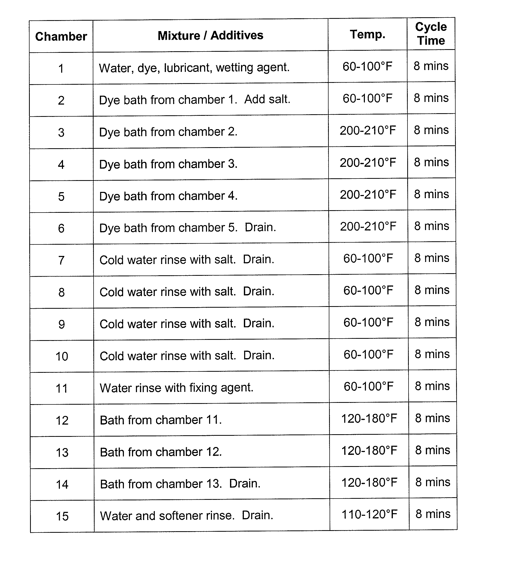
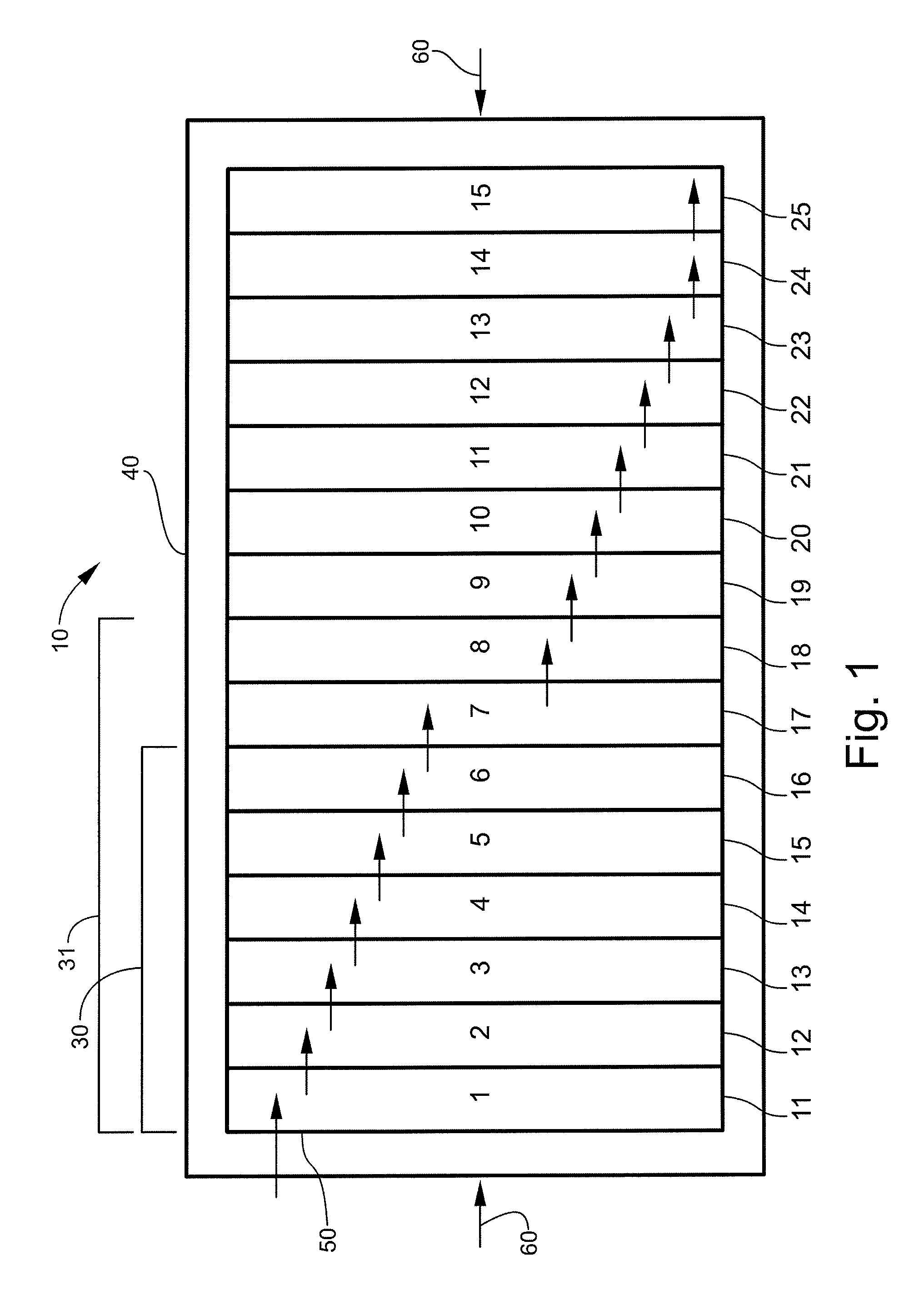
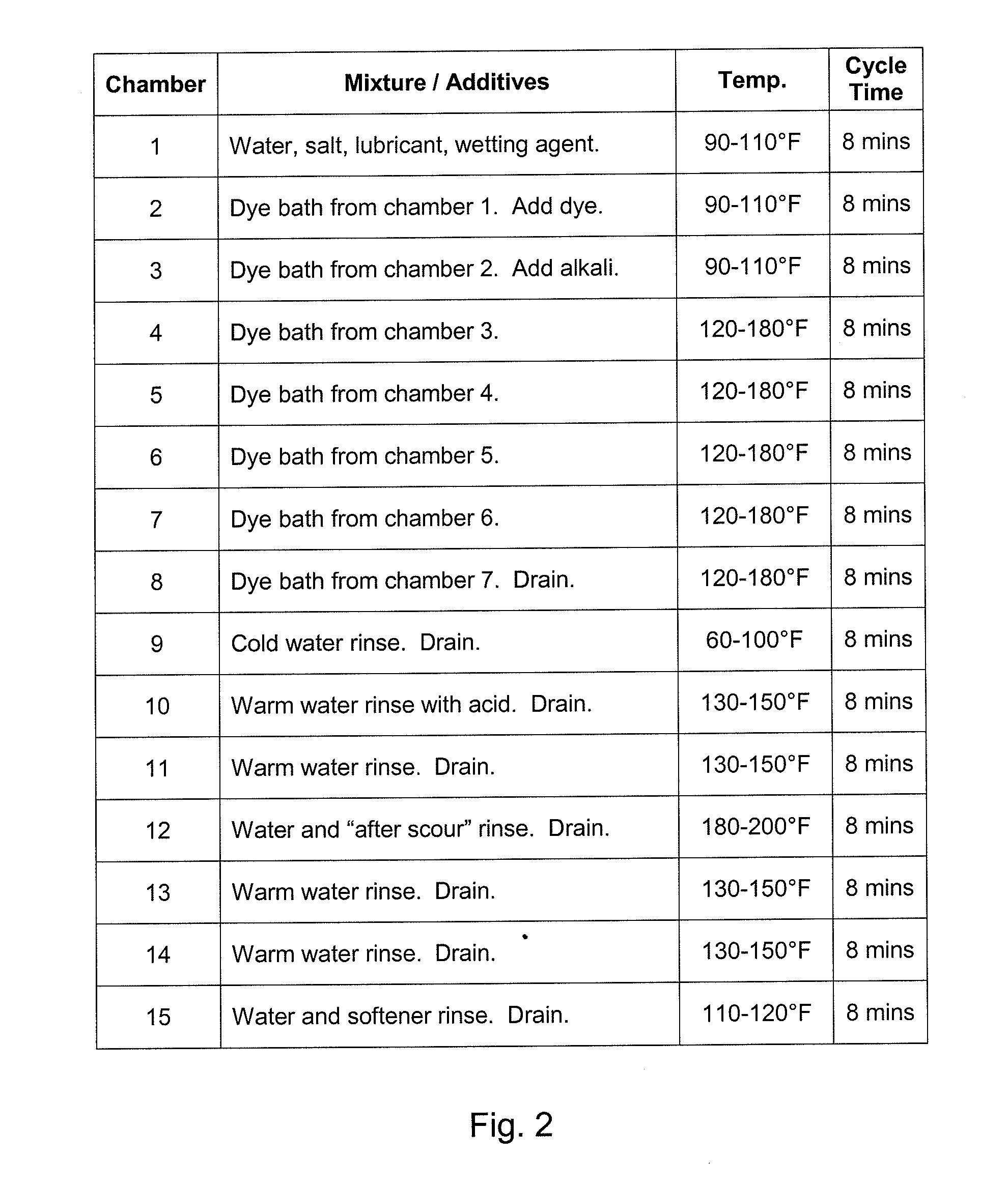
A fabric dyeing apparatus and / or method can include a tunnel, such as a modified bleaching tunnel, comprising a plurality of chambers through which a load of fabric is successively transferred. A first set of the chambers can include a consecutive series of dye chambers through which the fabric load and a single dye bath are successively transferred and in which the dye bath is heated to about the same temperature in each of the dye chambers. A first chamber in the series of dye chambers and each chamber subsequent to the dye chambers can be adapted to receive a fresh water bath. A last chamber in the series of dye chambers and each subsequent chamber can be adapted to drain the bath in those chambers. The weight ratio of dye bath mixture-to-fabric can be about 5:1. The dye bath can include a fiber reactive dye or a direct fabric dye.

Description

FIELD OF THE INVENTION[0001]The present invention relates to a fabric dyeing apparatus and method. Such an apparatus and / or method may be useful for saving time, materials, and cost related to dyeing fabric.BACKGROUND OF THE INVENTION[0002]Conventional commercial fabric dyeing processes can have certain economic, quality control, environmental, and other disadvantages. For example, the ratio of dye bath mixture-to-fabric in a conventional fabric dyeing process can be about 10:1, resulting in a high cost for water and chemical additives in the dye bath mixture. Another disadvantage is that, although “reactive dyeing” processes may provide greater color fastness and quality control, “direct dyeing” processes can be less expensive and are thus often used to dye fabric, resulting in lower quality products. When conventional “reactive dyeing” processes are employed to dye fabric in a commercial setting, processing time can be six hours or longer, which decreases productivity. Another dis...

Claims


Application Information

Patent Timeline
Patent Type & Authority Applications(United States)
IPC IPC(8): C09B62/00D06F33/00C09B67/22
CPCD06B5/26D06P1/0032D06B23/14
Inventor SELL, MICHAEL KEVINHARRIS, LARRY
Owner HBI BRANDED APPAREL ENTERPRISES
Learn More