Constant pressure pneumatic balancing tire inflation system

a tire inflation system and constant pressure technology, applied in the field of tire inflation systems, can solve the problems of tire pressure not being checked, air leakage from tires, and inability to manually check and maintain the target pressure for each tire,

Active Publication Date: 2012-02-02
HENDRICKSON USA L L C
View PDF15 Cites 67 Cited by
  • Summary
  • Abstract
  • Description
  • Claims
  • Application Information

AI Technical Summary

Benefits of technology

[0021]Yet another objective of the present invention is to provide a tire inflation system that enables balancing of pneumatic pressure across all of the tires in the system.
[0022]Still another objective of the present invention is to provide a tire inflation system that includes emergency protection of the tires in the event that one or more tires experiences a significant pressure loss.

Problems solved by technology

However, it is well known that air may leak from a tire, usually in a gradual manner, but sometimes rapidly if there is a problem with the tire, such as a defect or a puncture caused by a road hazard.
The large number of tires on any given heavy-duty vehicle setup makes it impractical to manually check and maintain the target pressure for each and every tire.
This difficulty is compounded by the fact that trailers of tractor-trailers or trucks in a fleet may be located at a site for an extended period of time, during which the tire pressure might not be checked.
Any one of these trailers or trucks might be placed into service at a moment's notice, leading to the possibility of operation with under-inflated or over-inflated tires.
Such operation may increase the chance of less-than-optimum performance and / or reduced life of a tire in service as compared to operation with tires at the target pressure, or within an optimum range of the target pressure.
Likewise, should a tire encounter a condition that causes it to become significantly over-inflated, such as increasing pressure from an increased ambient air temperature, the life and / or performance of the tire may be significantly reduced if the over-inflation continues unabated as the vehicle continues to travel.
The potential for significantly reduced tire life typically increases in vehicles such as trucks or tractor-trailers that travel for long distances and / or extended periods of time under such less-than-optimum inflation conditions.
Such a need to maintain the target pressure in each tire, and the inconvenience to the vehicle operator having to manually check and maintain a proper tire pressure that is at or near the target pressure, led to the development of prior art tire inflation systems.
While being satisfactory for their intended functions, tire inflation systems of the prior art may experience disadvantages in certain situations.
For example, a first disadvantage in the prior art is that many prior art tire inflation systems are not capable of deflation.
As a result, when the air pressure in a tire increases to a level that is greatly above the target pressure, typically due to increases in ambient air temperature, these systems are unable to reduce the pressure in the tires.
As a result, such prior art tire inflation systems may allow the tires to operate in a significantly over-inflated condition, which undesirably decreases performance of the tires and in turn decreases the life of the tires.
A second disadvantage occurs in prior art tire inflation systems that are capable of deflation.
More particularly, deflation-capable systems typically are electronically controlled, employing electronically-operated solenoid valves, electronic controllers, and other electronic components, which are expensive and are often complex to install and configure.
In addition, these electrical components require the use of the electrical system of the vehicle, which may be unreliable or even non-functional at times, in turn rendering the operation of the tire inflation system unreliable and potentially non-functional.
As a result, prior art deflation-capable tire inflation systems which are electronically controlled are often undesirably expensive, complex, and potentially undependable.
A third disadvantage is that most prior art tire inflation systems which are capable of deflation, and particularly electronically-controlled systems, are not constant-pressure systems and thus do not actively monitor tire pressure.
As a result, in most deflation-capable prior art tire inflation systems, when the system is not performing inflation or deflation, the pneumatic conduit of the system is exhausted to atmosphere.
Because such prior art systems are capable of only providing a periodic check of tire pressure, any inflation or deflation to bring the tires to the target pressure only takes place following the periodic check.
This lack of ability of prior art systems to continuously monitor tire pressure and dynamically respond to pressure changes undesirably reduces the ability of the system to actively or quickly respond to reduced tire pressure conditions, such as in the case of an air leak, and to increased tire pressure conditions, such as an increase in ambient temperature.
Moreover, as mentioned above, the electronic controls employed by prior art tire inflation systems are expensive, complex, and require power from the electrical system of the vehicle, which may be unreliable.
A fourth disadvantage of prior art tire inflation systems is that most systems, and particularly those prior art systems which are constant-pressure systems, do not provide balancing of pneumatic pressure across all of the tires in the system.
While such separate inflation of each tire is satisfactory for its intended purpose, such prior art systems are not capable of deflation of the tires, and thus are unable to reduce the pressure in the tires when it increases to a level that is greatly above the target pressure.
In addition, such prior art systems lack fluid communication between the tires.
Without fluid communication between the tires, different tires may be inflated to slightly different pressure levels, which is undesirable.
Although both wheels are designed to be the same diameter, their actual respective diameters are slightly different, since the lack of fluid communication between them causes them to be inflated to slightly different pressure levels.
Scrubbing of a tire causes premature wear on that tire, and undesirably shortens the life of the tire.
In addition, the lack of fluid communication between the tires undesirably increases the chance that a tire may operate with an excessively low inflation pressure.
For example, in the event that one tire in the system is about fifty percent (50%) below the target inflation pressure, a prior art system may take a significant amount of time to bring the pressure in the low tire up to the target pressure.
During that time, it is possible for the tire to be operated in a significantly under-inflated state, which decreases its life.
A fifth disadvantage of prior art tire inflation systems occurs in the few prior art systems which do provide balancing of pneumatic pressure across all of the tires.
However, these systems do not provide emergency protection of the tires in the event that one tire experiences a significant pressure loss.
In such a system, if the system is not isolated from a tire that is experiencing a significant pressure loss, the uniform inflation pressure of all of the tires may decrease significantly, which may place an excessive inflation demand on the system.
The system may not be able to meet this demand, which may result in the tires being operated below the target inflation pressure, in turn reducing tire life, and / or the system may actuate excessively to attempt to meet the demand, thereby reducing the life of the system.

Method used


Image

  • Constant pressure pneumatic balancing tire inflation system
  • Constant pressure pneumatic balancing tire inflation system
  • Constant pressure pneumatic balancing tire inflation system

Examples


first embodiment

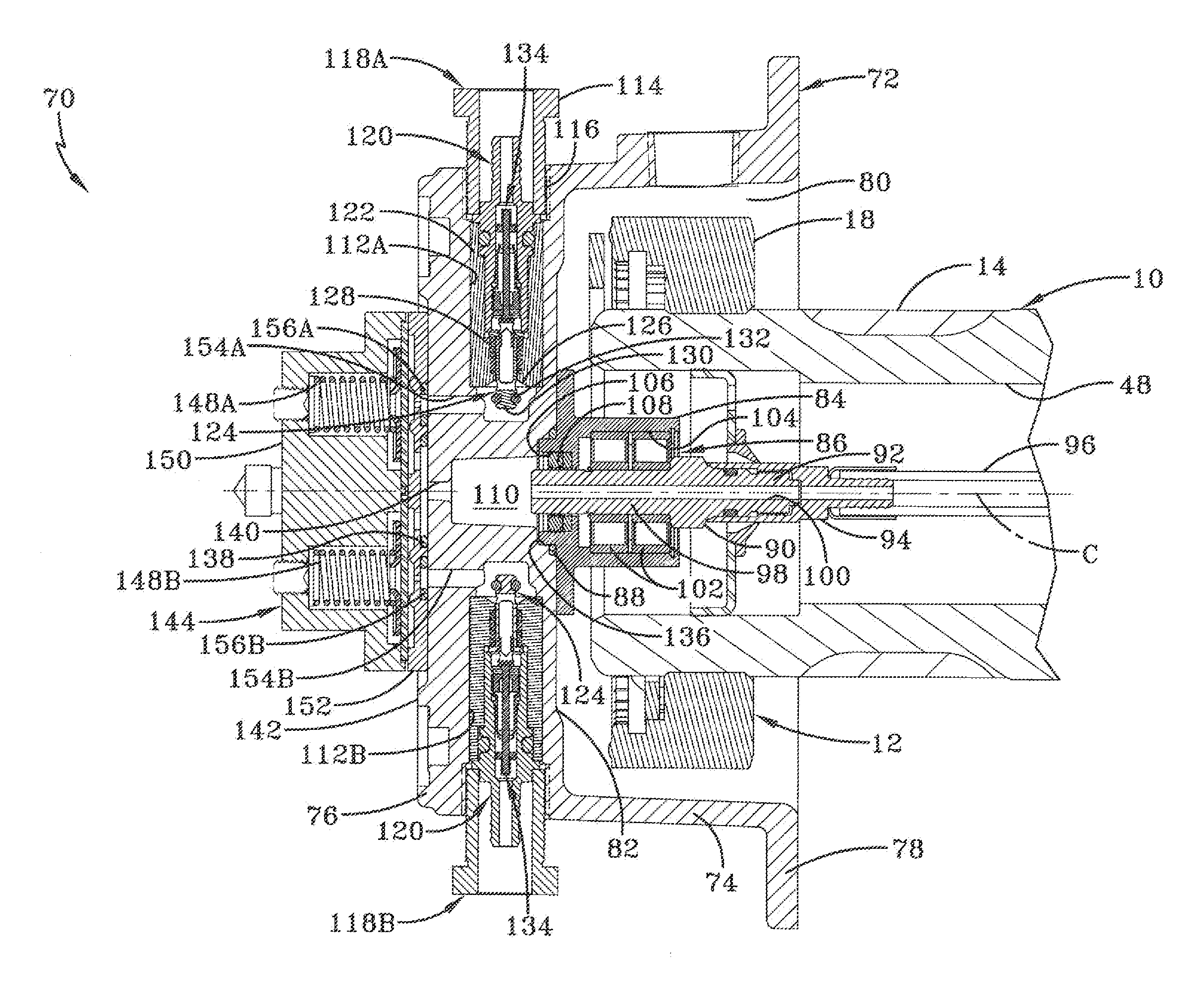
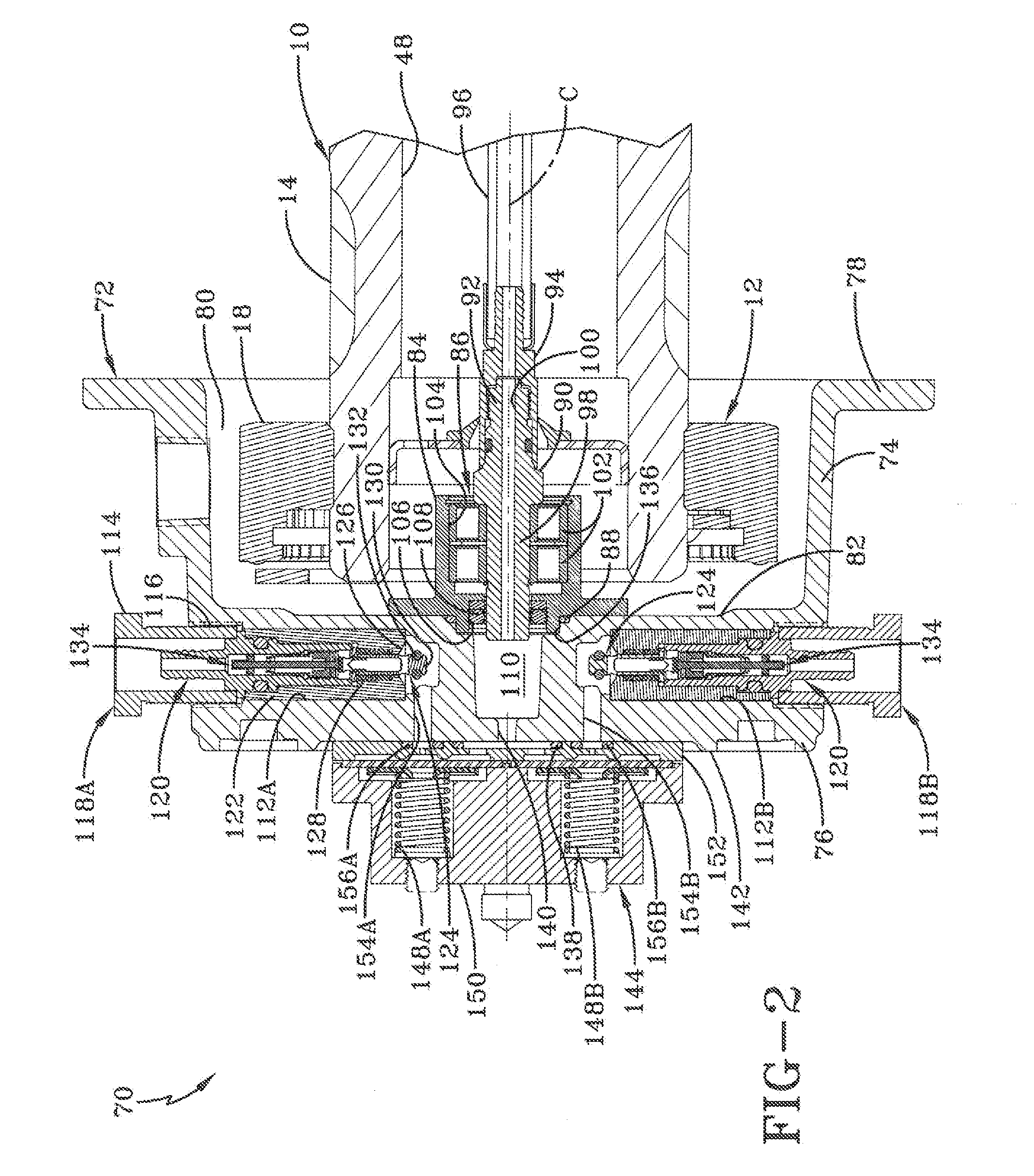
[0071]The structure of first embodiment tire inflation system 70 provides continuous balancing of pneumatic pressure across all of the tires in the system. More particularly, in a pneumatically balanced system 70, the tires are in fluid communication with one another, and according to the principles of fluid flow, all of the tires have a generally uniform, or balanced, inflation pressure. When this uniform inflation pressure is above the target pressure, the means that are employed to monitor the tire pressure enable tire inflation system 70 to decrease the uniform pressure by venting excess air to atmosphere as described above, which in turn respectively decreases the inflation pressure of all of the tires in the system to the target pressure. When this uniform inflation pressure is below the target pressure, the means that are employed to monitor the tire pressure enable tire inflation system 70 to increase the uniform pressure by supplying air from a vehicle air tank as described...

second exemplary embodiment

[0090]With particular, reference now to FIGS. 7-9 and 12A-12B, hub cap 176 of second exemplary embodiment tire inflation system 170 includes a cylindrical side wall 178. Intermediate wall 174 is integrally formed between an inboard end of hub cap 176 and an outboard end 200 of side wall 178, and preferably nearer to the side wall outboard end, and extends generally perpendicular to the side wall. It is to be understood that other shapes and configurations of hub cap side wall 178 and intermediate wall 174 may be employed without affecting the overall concept or operation of the present invention, such as an integrated dome or cone shape formed as one piece or multiple pieces, and / or adjusting the intermediate wall to be an outboard wall. A radially-extending flange 180 is formed on an inboard end of side wall 178, and is formed with a plurality of bolt openings 182 to enable bolts (not shown) to secure hub cap 176 to the outboard end of wheel hub 22 (FIG. 1). In this manner, hub cap...

second embodiment

[0102]The structure of second embodiment tire inflation system 170 provides continuous balancing of pneumatic pressure across all of the tires in the system. More particularly, in a pneumatically balanced system 170, the tires are in fluid communication with one another, se that and according to the principles of fluid flow, all of the tires have a generally uniform, or balanced, inflation pressure. When this uniform inflation pressure is above the target pressure, the means that are employed to monitor the tire pressure enable tire inflation system 170 to decrease the uniform pressure by venting excess air to atmosphere as described above, which in turn decreases the inflation pressure of all of the tires in the system to the target pressure. When this uniform inflation pressure is below the target pressure, the means that are employed to monitor the tire pressure enable tire inflation system 170 to increase the uniform pressure by supplying air from a vehicle air tank as described...


PUM


Abstract

A constant pressure vehicle tire inflation system includes an air supply source. A first wheel valve is in fluid communication with a first tire of the vehicle, and a second wheel valve is in fluid communication with a second tire of the vehicle. A pneumatic conduit extends between and is in fluid communication with the air supply source and the wheel valves. At least a portion of the pneumatic conduit remains charged with air from at least one of the supply source and the tires. The system includes means for distributing air flow between the pneumatic conduit and the first and second wheel valves, in which the wheel valves and the means selectively maintain fluid communication between the first and second tires and the pneumatic conduit to provide pneumatic balancing between the tires, and the wheel valves provide emergency protection when a tire experiences significant pressure loss.

Description

CROSS-REFERENCE TO RELATED APPLICATIONS[0001]This application claims the benefit of U.S. Provisional Patent Application Ser. No. 61 / 369,163, which was filed on Jul. 30, 2010.BACKGROUND OF THE INVENTION[0002]1. Technical Field[0003]The invention relates to the art of tire inflation systems. More particularly, the invention relates to tire inflation systems for heavy-duty vehicles such as trucks and tractor-trailers or semi-trailers, which can operate as the vehicle is moving. Still more particularly, the invention is directed to a tire inflation system that is a constant pressure system which continuously balances pneumatic pressure across all of the tires in the system, and provides emergency protection in the event a tire in the system experiences significant pressure loss.[0004]2. Background Art[0005]Heavy-duty vehicles typically include trucks and tractor-trailers or semi-trailers. Tractor-trailers and semi-trailers, which shall collectively be referred to as tractor-trailers for...

Claims


Application Information

Patent Timeline
Patent Type & Authority Applications(United States)
IPC IPC(8): B60C23/00
CPCB60C23/003B60C23/007B60C23/008B60C23/009B60C23/00318B60C23/00327B60C23/00336B60C23/00354B60C23/00363
Inventor WILSON, MATT J.CERVANTEZ, JESSE W.PADULA, SANTOMORRIS, JEFFREY S.
Owner HENDRICKSON USA L L C
Why Eureka
Try Eureka