Showerhead

a showerhead and shower head technology, applied in the field of showerheads, can solve the problems of affecting the service life the failure of the whole conventional showerhead b>100/b>, and the long time-consuming of the step of inserting the gas tubes into the openings of the bottom portion b>110/b>, so as to improve the ability to bear high temperature, thermal cycling and corrosion, and prolong the li

Inactive Publication Date: 2012-02-02
HERMES EPITEK
View PDF0 Cites 176 Cited by
  • Summary
  • Abstract
  • Description
  • Claims
  • Application Information

AI Technical Summary

Benefits of technology

[0012]According to the showerhead of the present invention, the gas holes are formed on the bottom plate and the channel plate. There is no need to use gas tubes. Different process gases will not be mixed within the showerhead. The leakage caused by clearances between the gas tubes and

Problems solved by technology

Therefore, the step of inserting the gas tubes 120 into the openings of the bottom portion 110 may cost a long period of time.
Any one of the gas tubes 120 which is not soldered properly may cause the whole conventional showerhea

Method used


Image

  • Showerhead
  • Showerhead
  • Showerhead

Examples


Embodiment Construction

[0019]The detailed description of the present invention will be discussed in the following embodiments, which are not intended to limit the scope of the present invention, but can be adapted for other applications. While drawings are illustrated in detail, it is appreciated that the quantity of the disclosed components may be greater or less than that disclosed, except where expressly restricting the amount of the components.

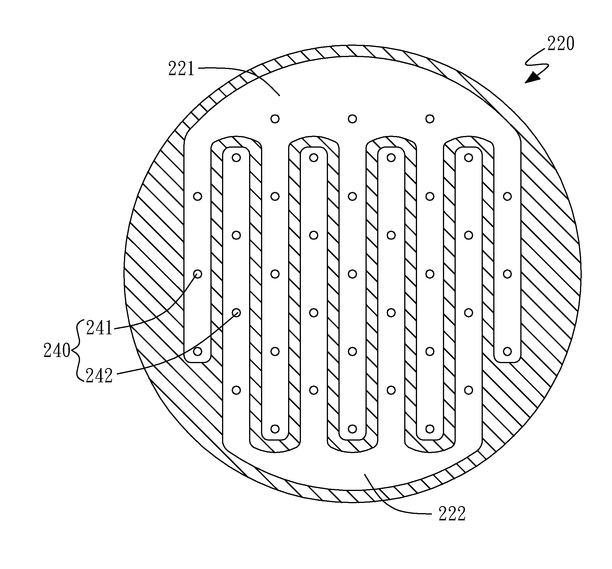
[0020]FIG. 3A shows a sectional view of a showerhead 200 in accordance with an embodiment of the present invention. The showerhead 200 includes a bottom plate 210, a channel plate 220, and a top plate 230. The bottom plate 210 includes a plurality of cooling channels 211 and a plurality of gas holes 240. The cooling fluid, such as water, can flow into the cooling channels 211 for cooling the showerhead 200. The gas holes 240 includes at least one first gas hole 241 and at least one second gas hole 242. The channel plate 220 includes a first trench area 221 and a...


PUM

PropertyMeasurementUnit
Timeaaaaaaaaaa
Areaaaaaaaaaaa

Abstract

A showerhead is disclosed in this invention. The showerhead includes a bottom plate, a channel plate, and a top plate. The bottom plate includes a plurality of cooling channels and a plurality of gas holes, wherein the gas holes includes at least one first gas hole and at least one second gas hole. The channel plate includes a first trench area and a second trench area, wherein the first gas hole is connected with the first trench area, and the second gas hole is connected with the second trench area. The top plate is coupled to the channel plate.

Description

BACKGROUND OF THE INVENTION[0001]1. Field of the Invention[0002]The present invention generally relates to semiconductor equipment, and more particularly to a showerhead.[0003]2. Description of Related Art[0004]Semiconductor manufacturing equipment is commonly used in the production of semiconductor components. The semiconductor manufacturing equipment typically has a reaction chamber. The reaction gases which are required by the semiconductor manufacturing process can be provided into the reaction chamber by the showerhead of the reaction chamber. FIG. 1 shows a sectional view of a conventional showerhead 100. The conventional showerhead 100 includes a bottom portion 110, a plurality of gas tubes 120, a first plate 131, a second plate 132, and a top portion 140. The gas tubes 120 include a plurality of first gas tubes 121 and a plurality of second gas tubes 122. Moreover, the conventional showerhead 100 includes a first space 191, a second space 192, and a third space 193. A first ...

Claims


Application Information

Patent Timeline
IPC IPC(8): H01L21/306B23P15/16
CPCB23P15/16Y10T29/49433C23C16/45572C23C16/45565
Inventor HUANG, CHIEN-PINGHUANG, TSAN-HUA
Owner HERMES EPITEK
Why Eureka
Try Eureka