Rear handle

a technology for handles and power tools, applied in the field of handles for power tools, can solve problems such as generating a large amount of vibration

Active Publication Date: 2012-02-09
BLACK & DECKER INC
View PDF3 Cites 34 Cited by
  • Summary
  • Abstract
  • Description
  • Claims
  • Application Information

AI Technical Summary

Problems solved by technology

During the operation of such hammers, a considerable amount of vibration can be generated.
The transfer of vibration to the rear handle from the body, and subsequently to the operator's hand can not only be painful but can result in injury, particularly when the hammer drill is used over long periods of time.

Method used


Image

  • Rear handle
  • Rear handle
  • Rear handle

Examples


Embodiment Construction

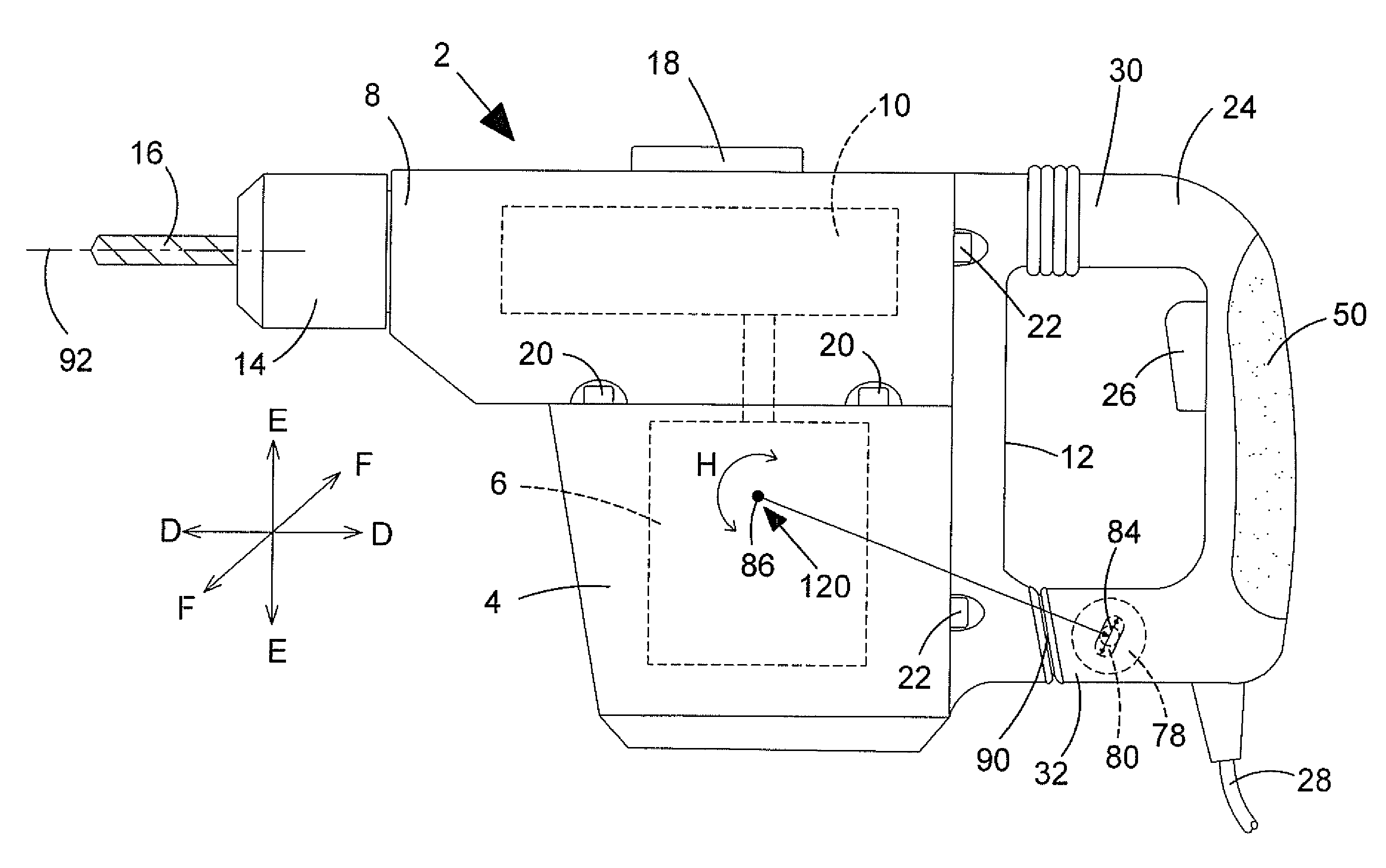
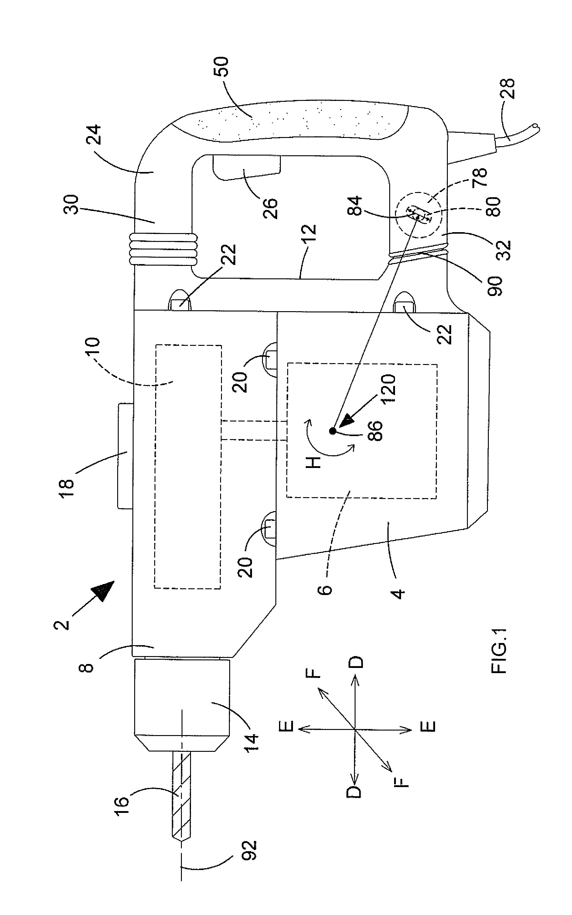
[0026]Referring to FIG. 1, a hammer drill comprises a main housing 2 which comprises a motor housing 4, in which is mounted an electric motor 6, a gear housing 8 in which is mounted a rotary drive and hammer mechanism 10, and a rear housing 12. The motor housing 4 is connected to the gear housing using bolts 20. Similarly, the rear housing 12 is attached to both of the motor housing 4 and gear housing 8 using bolts 22. A tool holder 14 is mounted on the front of the gear housing 8 which is capable of holding a cutting tool 16, such as a drill bit. The motor 6 rotatingly and / or reciprocatingly drives the cutting tool 16 via the rotary drive and / or hammer mechanism 10. The hammer drill can operate in three modes of operation, namely hammer only mode, drill only mode and combined hammer and drill mode. A mode change knob 18 is rotatably mounted on the top of the gear housing 8. Rotation of the knob 18 to predetermined angular positions activates or deactivates the rotary drive and / or h...


PUM


Abstract

A power tool, for example a hammer drill comprising: a housing; a handle having two ends, the first end being moveably mounted to the housing via a first mounting assembly, the second end being moveably mounted to the housing via a second mounting assembly; wherein the first mounting assembly comprises: a first part mounted on the housing and a second part mounted on the first end of the handle, one part comprising a sleeve, the other part comprising a rod mounted in an axially slideable manner in the sleeve to enable the first end of the handle to slide towards or away from the housing; and a biasing mechanism connected between the two parts which biases the first end of the handle away from the housing; wherein the second mounting assembly comprises: a third part mounted on the body and a fourth part mounted on the second end of the handle, one part comprising a support, the other part comprising a pin located in the support which is capable of being rotated in the support to enable the second end of the handle to rotate relative to the housing and to move linearly in the support to enable the second end of the handle to move linearly relative to the housing; characterized in that the support comprises a passage in which the pin is located, the pin being capable of freely moving within the passage either rotationally to enable the second end of the handle to rotate relative to the housing or linearly to enable the second end of the handle to move linearly relative to the housing.

Description

CROSS-REFERENCE TO RELATED APPLICATIONS[0001]This application claims priority, under 35 U.S.C. §119(a)-(d), to UK Patent Application No. GB 10 131 75.3 filed Aug. 5, 2010, the contents of which is incorporated herein by reference in its entirety. The disclosure of GB 2456805 which was filed on Jul. 29, 2009 is also incorporated herein by reference in its entirety.FIELD OF THE INVENTION[0002]The present invention relates to a handle for a power tool, in particular for a hammer drill, and in particular, to a mounting assembly for a rear handle on a hammer drill which reduces the amount of vibration transmitted to the handle.BACKGROUND OF THE INVENTION[0003]Power tools of all types comprise a body attached to which are handles by which an operator can support the tool. Vibrations are generated in the body during the operation of such tools which are transferred to the handles. It is desirable to minimize the amount of transfer.[0004]A hammer drill can operate in one or more of the foll...

Claims


Application Information

Patent Timeline
Patent Type & Authority Applications(United States)
IPC IPC(8): B25D17/24
CPCB25D17/043B25D2250/371B25D2250/121B25F5/006B25D17/24B25F5/026
Inventor ROBERTS, ANA-MARIAFRIEDRICH, ANDREAS
Owner BLACK & DECKER INC
Why Eureka
Try Eureka