Turbine engine seals

a technology for turbine engines and seals, which is applied in the field of turbine engine seals, can solve the problems of reducing affecting the service life of the engine, so as to achieve the effect of reducing the risk of engine damage, and improving service li

Active Publication Date: 2012-02-23
GENERAL ELECTRIC CO
View PDF4 Cites 49 Cited by
  • Summary
  • Abstract
  • Description
  • Claims
  • Application Information

AI Technical Summary

Problems solved by technology

However, operational transient conditions, which, for example, may include engine startup, shutdown, or load swings, often result in axial movement and radial expansion of the rotating parts in relation to stationary parts, which may cause the teeth or other structures that define the labyrinth seal on one radial surface to contact or collide with the teeth or structures on the opposing radial surface.
This contact typically results in the w

Method used


Image

  • Turbine engine seals
  • Turbine engine seals
  • Turbine engine seals

Examples


Embodiment Construction

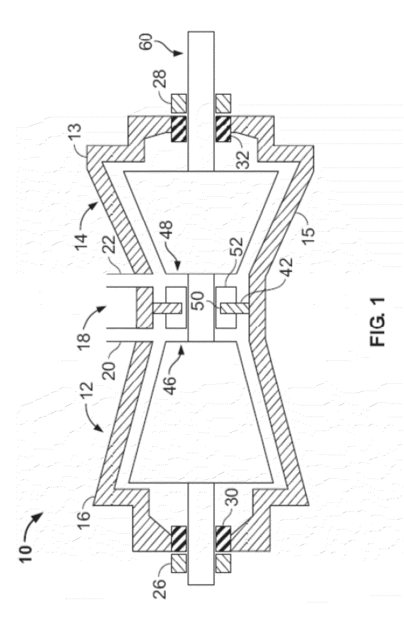
[0015]At least one aspect of the present invention is described below in reference to its application in connection with and operation of a steam turbine. However, it should be apparent to those skilled in the art and guided by the teachings herein that the present invention is likewise applicable to any suitable engine, gas turbine, steam turbine, turbine or turbine engine.

[0016]In addition, several descriptive terms may be used herein. The meaning for these terms shall include the following definitions. As used herein, “downstream” and “upstream” are terms that indicate a direction relative to the flow of working fluid through the turbine. As such, the term “downstream” means the direction of the flow, and the term “upstream” means in the opposite direction of the flow through the turbine. Related to these terms, the terms “aft” and / or “trailing edge” refer to the downstream direction, the downstream end and / or in the direction of the downstream end of the component being describe...


PUM


Abstract

A seal is provided for preventing axial leakage through a radial gap between a stationary structure and a rotating structure. The radial gap is defined by an inner radial surface opposing an outer radial surface across the radial gap. The seal includes at least one land disposed on one of the inner radial surface and outer radial surface. At least one first tooth and at least one second tooth project from the other of the radial surfaces. The second tooth is shorter than the first tooth. At least one of the first tooth and second tooth, is configured to extend at an angle upstream. This angle is defined between a radial surface from which the first or second tooth projects and an upstream surface of the same tooth. The angle is less than or equal to about 80 degrees.

Description

BACKGROUND OF THE INVENTION[0001]The present invention relates generally to systems and apparatus for improving the efficiency and operation of turbine engines, which, as used here and unless specifically stated otherwise, is meant to include all types of turbine or rotary engines, including steam turbine engines, combustion turbine engines, aircraft engines, power generation engines, and others. More specifically, but not by way of limitation, the present invention relates to systems and apparatus pertaining to seals for turbine engines and, specifically, to minimizing leakage flow between stationary and rotating parts of a turbine engine.[0002]In many turbine engines, labyrinth seals are often used as a means of minimizing the leakage of working fluid between stationary and rotating parts. These stationary and rotating parts are generally radial in shape. In general, these seals include, on either the stationary or rotating part, multiple axially spaced teeth that are either machi...

Claims


Application Information

Patent Timeline
IPC IPC(8): F16J15/447
CPCF01D11/001F01D11/02F05D2250/232F16J15/4472F16J15/441
Inventor ZENG, XIAOQIANGSLEPSKI, JONATHON EDWARDGUO, TAOJOHN, JOSHYNEELI, SUDHAKAR
Owner GENERAL ELECTRIC CO
Why Eureka
Try Eureka