

Digital camera
- Summary
- Abstract
- Description
- Claims
- Application Information
AI Technical Summary
Benefits of technology
Problems solved by technology
Method used
Image

Examples
first embodiment
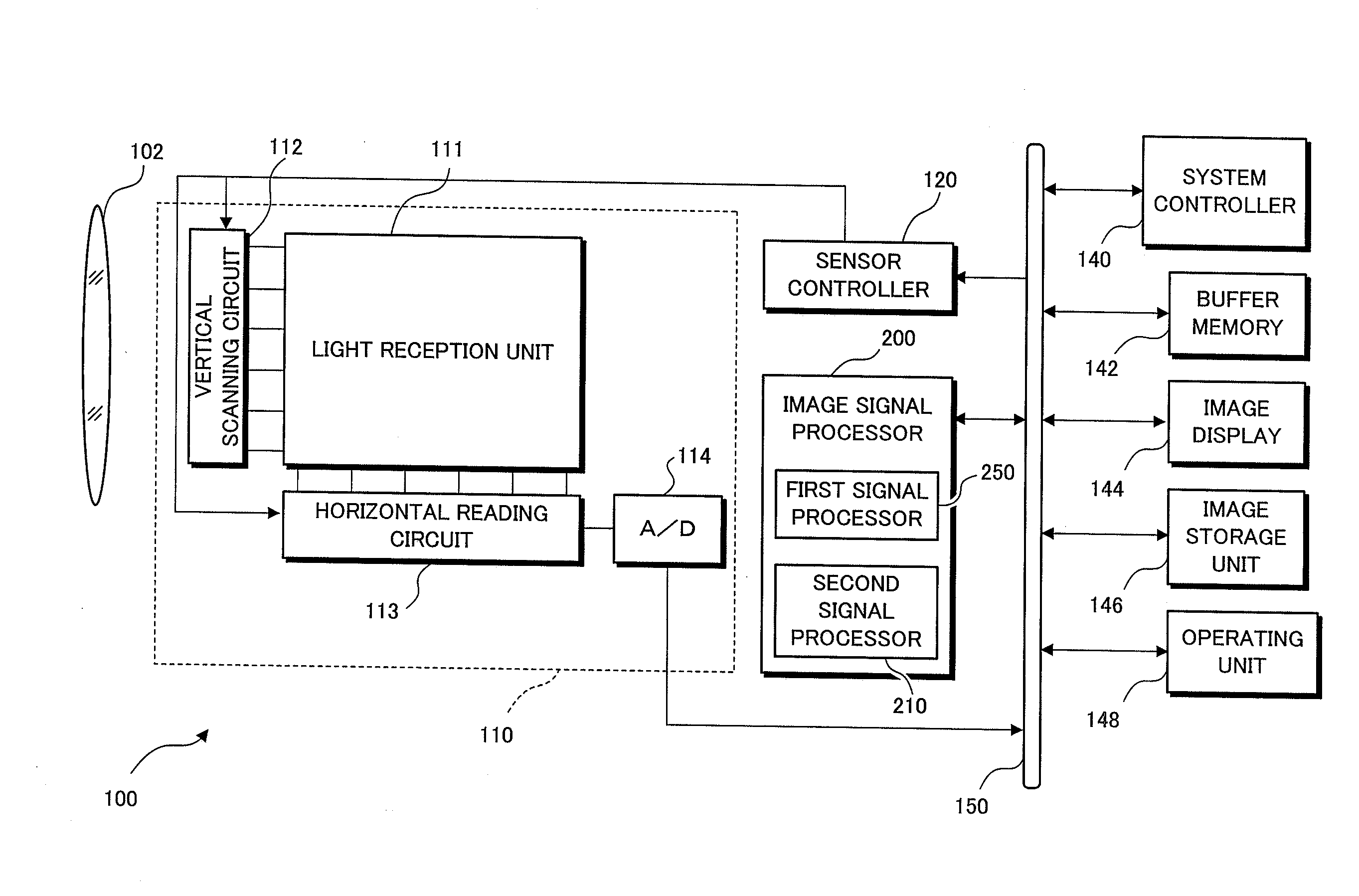
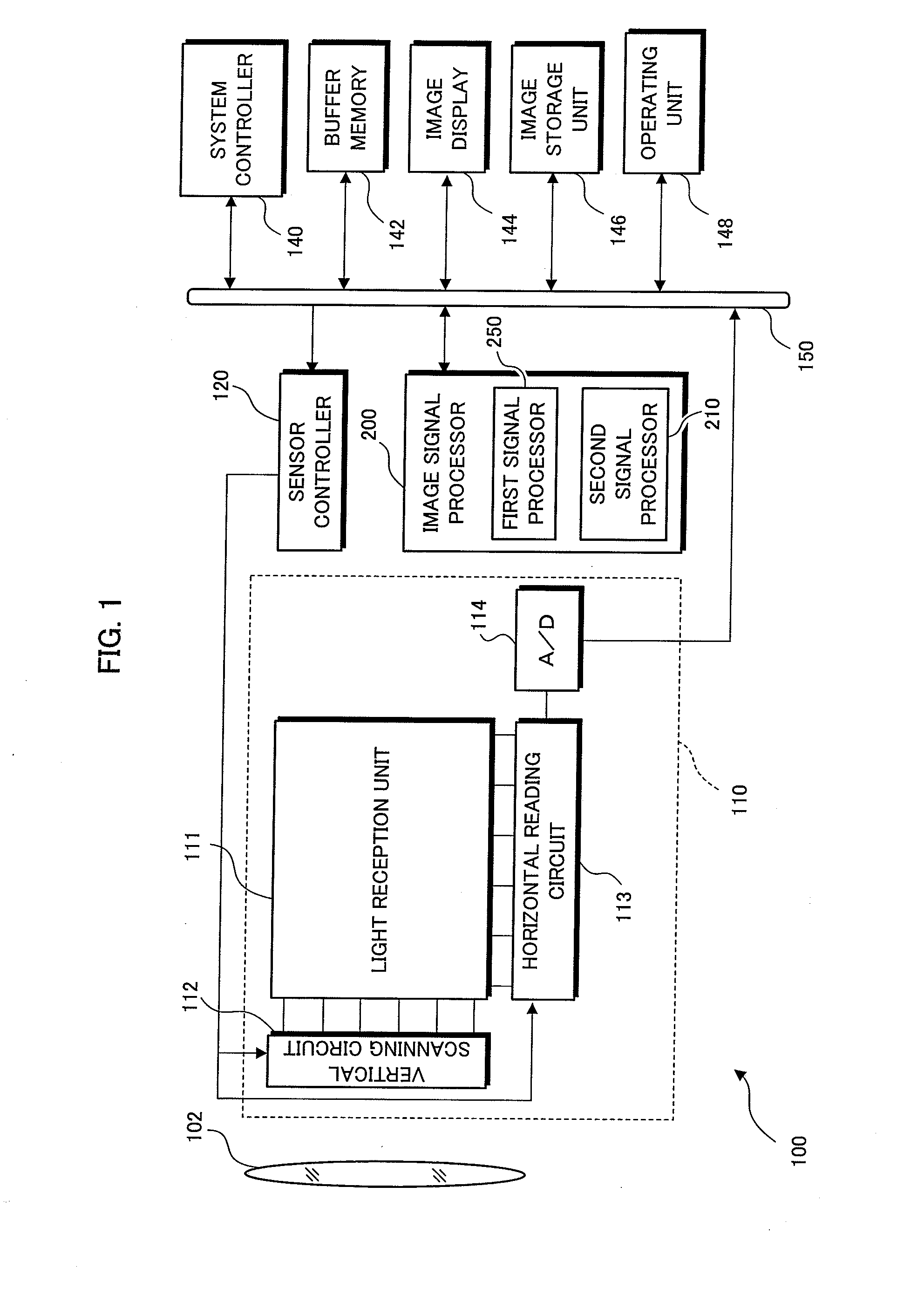
[0033]FIG. 1 is a block diagram illustrating the schematic constitution of a digital camera to which this invention is applied. In this embodiment of this invention, a digital camera 100 will be described as a digital still camera. Needless to say, this invention may also be applied to a digital movie camera or the like capable of photographing still images.
[0034]The digital camera 100 includes an image pickup lens 102, an imaging device 110, a sensor controller 120, an image signal processor 200, a system controller 140, a buffer memory 142, an image display 144, an image storage unit 146, an operating unit 148, and a system bus 150.
[0035]The imaging device 110, the sensor controller 120, the image signal processor 200, the system controller 140, the buffer memory 142, the image display 144, the image storage unit 146, and the operating unit 148 are electrically connected via the system bus 150.
[0036]The system controller 140 is constituted by a CPU or the like, and performs overal...
second embodiment
[0091]FIG. 4 is a schematic view showing an example of an array of color filters provided on photodiodes (photoelectric conversion units) arranged two-dimensionally on the light reception unit 111 of the imaging device 110 provided in the digital camera 100 according to a second embodiment of this invention. FIG. 4A shows an arrangement of color filters in all colors, while FIG. 4B shows an arrangement in which the color filters of three colors, namely R, G, B are extracted from the arrangement shown in FIG. 4A.
[0092]As shown in FIG. 4A, the imaging device 110 includes color filters in a total of fifteen colors, namely λ1, λ2, . . . , λ2 in addition to R, G, B. Further, as shown in FIG. 4B, the number of arranged G filters is twice that of the other colors, and therefore, focusing solely on the arrangement of the R, G, B color filters, a Bayer array is realized. Likewise in this embodiment, spectral sensitivity characteristics determined from combinations of the respective spectral ...
third embodiment
[0106]FIG. 5 is a schematic view showing an example of an array of color filters provided on photodiodes (photoelectric conversion units) arranged two-dimensionally on the light reception unit 111 of the imaging device 110 provided in the digital camera 100 according to a third embodiment of this invention. FIG. 5A shows a regular array of color filters in nine colors, namely λ1 to λ9. Likewise in this embodiment, spectral sensitivity characteristics determined from combinations of the respective spectral transmission characteristics of the color filters in the nine colors λ1, λ2, . . . , λ9 and the spectral sensitivity characteristics of the photoelectric conversion units (photodiodes) arranged on the imaging device 110 will be referred to as the spectral sensitivity characteristic of the λ1 pixel, the spectral sensitivity characteristic of the λ2 pixel, . . . , and the spectral sensitivity characteristic of the λ9 pixel.
[0107]FIG. 5B is a view showing the manner in which image sig...
PUM
 Abstract
Description
Claims
Application Information