Wave gear device

Active Publication Date: 2007-07-12
HARMONIC DRIVE SYST IND CO LTD
View PDF6 Cites 22 Cited by
  • Summary
  • Abstract
  • Description
  • Claims
  • Application Information

AI Technical Summary

Benefits of technology

[0013] When a bearing mechanism designed to hold the wave generator and flexible external gear while allowing them to rotate relative to each other is configured in this manner, rolling fatigue does not occur because the rolling elements of the wave bearing do not rotate during high-speed rotation. Also, rolling fatigue of the outer ring and other components commonly caused by centrifugal force acting on the rolling elements does not occur because the rolling elements do not rotate or revolve. Furthermore, the life of the ball bearings due to inadequate lubrication can be prev

Problems solved by technology

On the other hand, the relative sliding velocity between the wave generator and the flexible external gear is low during low-speed

Method used


Image

  • Wave gear device
  • Wave gear device
  • Wave gear device

Examples


Example

[0035](Symbols) 1, 1Awave gear device 2rigid internal gear24internal teeth 3flexible external gear 3ainternal peripheral surface portion34external teeth 4wave generator41input shaft42rigid plug43wave bearing44inner ring45outer ring45aexternal peripheral surface of the outer ring46balls47retainer 5elastic ring 7partition piece 8split side plate pieces81main body member82frictional contact member82africtional contact surface 9lubrication oil film10restraining member11restraining plate11bmain body member11cfrictional contact member11dfrictional contact surface11eguide holes12elastic ring13guide pin

BEST MODE FOR CARRYING OUT THE INVENTION

[0036] A wave gear device in which the present invention has been applied is described below with reference to the drawings.

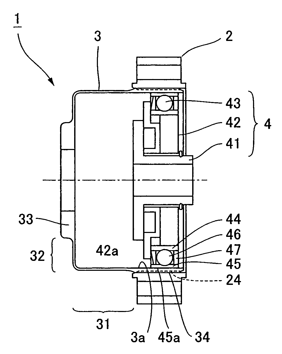
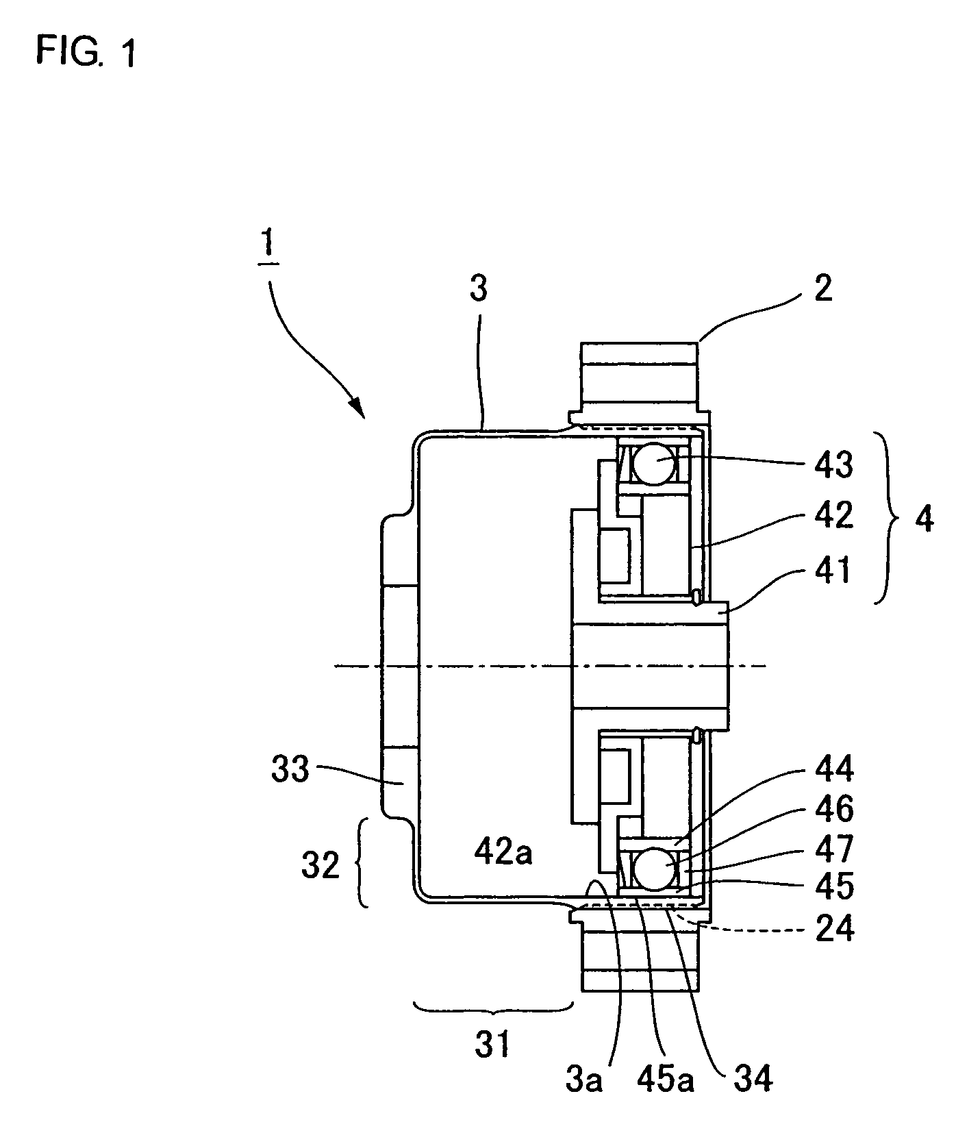
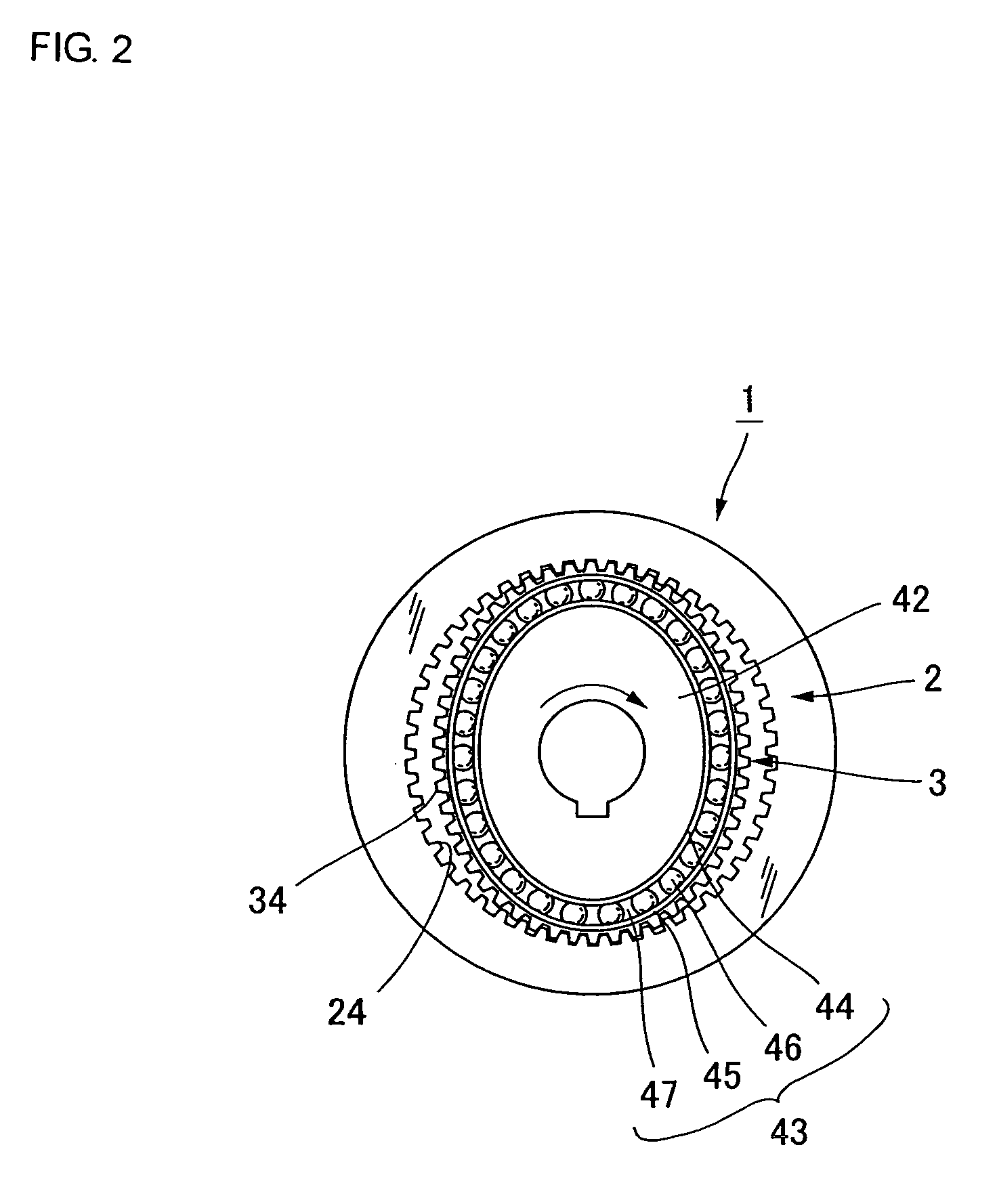
[0037]FIG. 1 is a longitudinal sectional view showing a wave gear device. FIG. 2 is a cross-sectional block diagram of the device sectioned along the surface orthogonal to the axis. The wave gear device 1 is a so-called “cup-shap...


PUM


Abstract

A wave gear device (1), wherein when a wave generator (4) is in a low speed rotating state, a rolling bearing state is formed by a wave bearing (43) and the wave generator (4) and a flexible external gear (3) are held in a relatively rotatable state and when the wave generator (4) is in a high speed rotating state, partition pieces (7) and split side plate pieces (8) forming the retainer (47) of the web bearing (43) are displaced to the outside to stop the rotation of balls (46) in their axes and the revolution thereof. Accordingly, a sliding bearing state is formed by lubricating oil film (9) formed between the wave generator (4) and the flexible external gear (3) and the wave generator and the flexible external gear are held in a relatively rotatable state. When the wave generator (4) returns to the low speed state, the constraint of the wave bearing (43) is released by the elastic return force of the elastic ring (5) of the retainer (47) and the wave bearing (43) returns to the rolling bearing state. Since a rolling fatigue does not occur on the wave bearing (43) in high speed rotation, the wave gear device allowing the input of the high speed rotation therein can be realized.

Description

TECHNICAL FIELD [0001] The present invention relates to a wave gear device that can handle high speed rotations suitable for use in reducing the high speed output rotations of a gas turbine or other high-speed power sources. BACKGROUND ART [0002] A typical wave gear device comprises an annular rigid internal gear, an annular flexible external gear coaxially disposed inside the rigid internal gear, and an elliptically contoured wave generator fitted inside the flexible external gear. The flexible external gear is elliptically flexed by the wave generator, and meshes with the rigid internal gear at the two ends of the elliptical shape in the direction of the major axis. The two gears have a tooth number difference of 2n teeth (where n is a positive integer). Therefore, when the wave generator is rotated by a motor or another rotational drive source, the meshing location of the two gears moves in the circumferential direction, and a relative rotation corresponding to the tooth number d...

Claims


Application Information

Patent Timeline
IPC IPC(8): F16H35/00F16C19/52F16C21/00F16C33/38F16C39/02F16C41/00F16H1/32F16H49/00
CPCF16C19/52F16C21/00Y10T74/19F16C39/02F16H49/001F16C33/3812F16C2361/61
Inventor KIYOSAWA, YOSHIHIDE
Owner HARMONIC DRIVE SYST IND CO LTD
Why Eureka
Try Eureka