Method and Device for Environmental and Health Monitoring

Inactive Publication Date: 2015-11-19
LAW SUI CHUN +1
2 Cites 43 Cited by

AI-Extracted Technical Summary

Problems solved by technology

Nevertheless, the prices of this type of instruments are significantly high.
The operations of these instruments are complicated and only manageable by well trained and skillful technicians.
The size of this type of instrument is therefore comparatively compact.
For examples, to measure the concentration of the volatile organic compounds solely by the photo...

Method used

[0235]FIG. 7 indicates the circuit of carbon dioxide sensor 15. In the present embodiment, the carbon dioxide sensor 15 belongs to a heated metal oxide type. A heating element is included in addition to the sensor element. The resistance of the sensor changes with the concentration of carbon dioxide. The input voltage first go through the resistor, it will then be amplified by an analog amplifier and be sent to the control unit 20. In order to obtain an accurate value for carbon dioxide, the desired operation temperature of the sensor is maintained by the built-in heater. The influence of the environmental temperature and ambient carbon dioxide is eliminated by comparing the voltage output obtained with that of the ambient air. A more accurate result is obtained. In addition, the internal temperature of the sensor by the heating element is fed to control unit 20. This acts as a reference for showing that the sensor has been warmed-up, and indicating that sensor has reached the optimal operation temperature.
[0242]Further refer to the FIG. 10, the first conditional array showing the environmental parameters of temperature and total volatile organic compound are employed for assessment of the level of formaldehyde. When the temperature is within the range of 25.5° C. to <35° C. (which i...

Benefits of technology

[0008]At least one advantage of the present invention is to address the deficiencies of current environmental monitoring devices and methods.
[0009]It has the further advantage to provide a device and a method for environmental monitoring and analyzing. Different levels of the environmental parameters are detected and measured at the same time. They are then judged and analyzed systematically.
[0010]It has the further advantage to provide a systematically analyzing and health assessment on the co-relationship between the different obtained environmental parameters and the health parameters and/or conditions of the occupants. The health assessment further includes the assessment and evaluation related to the possible disease and health risk on respiratory system of the occupants by the environmental parameter. Based on the result of the health assessment, the d...

Abstract

The present invention is related to an environmental monitoring and analyzing device. The device contains a plurality of sensors, a control unit and a display unit. The different types of sensor obtain values of different environmental parameters. The control unit receives the obtained values of the environmental parameters and compares the obtained values against predetermined standards and criteria which define parameter ranges of the different environmental parameters. A display unit displays a real-time air quality report comprising a user-friendly interpretation of the obtained values and recommendations in response to the obtained values. The present invention record and analyze the cause and consequence on the changed of level of different environmental parameters at different time duration, it also provide a tool to record and analyze the cause of some possible disease of the occupants.

Application Domain

SamplingWeather condition prediction +5

Technology Topic

EngineeringEnvironmental monitoring +4

Image

  • Method and Device for Environmental and Health Monitoring
  • Method and Device for Environmental and Health Monitoring
  • Method and Device for Environmental and Health Monitoring

Examples

  • Experimental program(1)

Example

DETAILED DESCRIPTION OF THE DRAWINGS
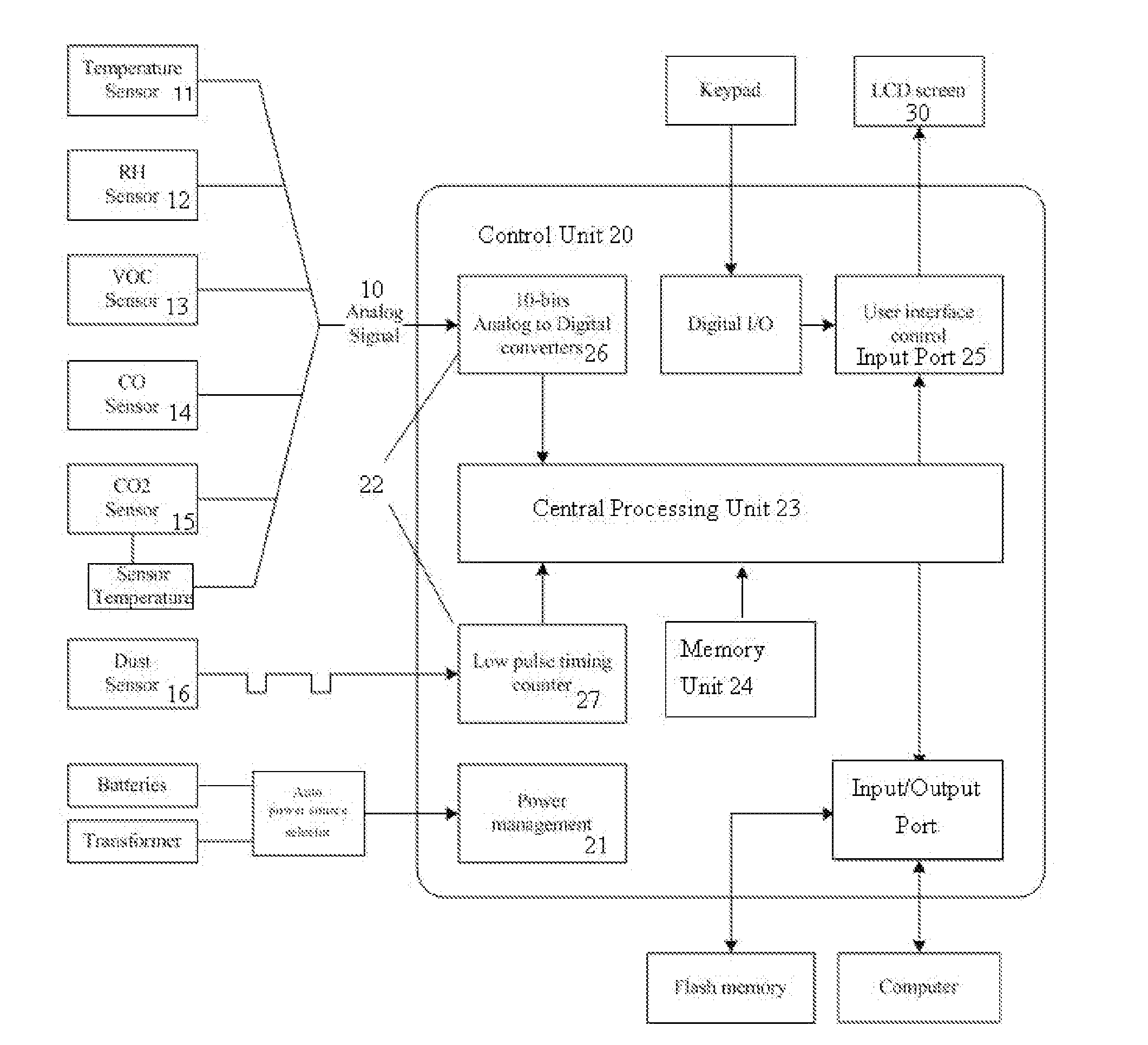
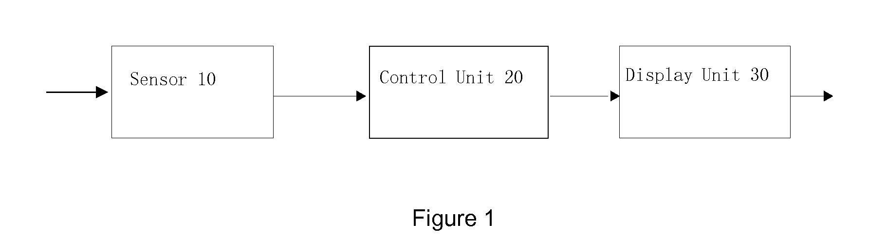
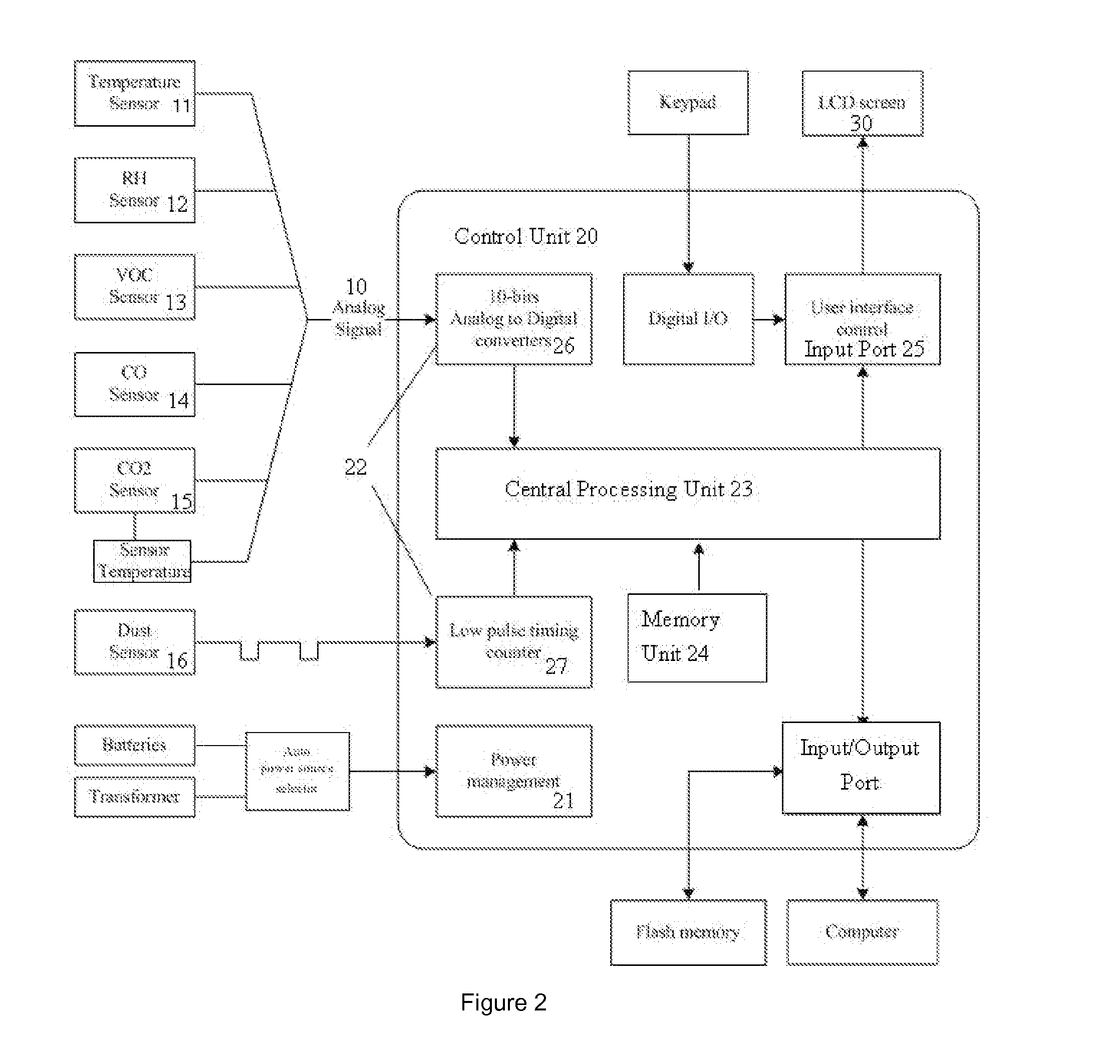
[0229]Referring to FIGS. 1 and 2, the device of the present invention contains the sensors 10, the control unit 20 and the display unit 30.
[0230]The sensors 10 obtain the values of different environmental parameters. The control unit 20 collects the obtained values. In the present embodiment, the sensors 10 are a temperature sensor, a relative humidity sensor 12, a volatile organic compounds sensor 13, a carbon monoxide sensor 14, a carbon dioxide sensor 15, and a respirable suspended particulates sensor 16. Other environmental sensors such as the ozone sensor, the nitrogen dioxide sensor, the air flow rate sensor, the radon level sensor and the formaldehyde sensor can be applied for the same purpose.
[0231]FIGS. 3-8 indicate the circuit diagrams for the sensors in the embodiment of the present invention. The circuit for the temperature sensor 11 is shown in FIG. 3. In the present embodiment, a thermistor in which its resistance varies with the temperature is employed as the temperature sensor. The change of temperature in the environment results the change of the resistance of the thermistor RT. The change of thermistor RT can be represented by the voltage output. The control unit 20 receives the output voltage Vol. The output of the temperature sensor belongs to a chain of periodic signals, whereas the frequencies of the periodic signals are temperature dependent. The control unit 20 detects the frequency of the waveform and determines the measured temperature.
[0232]FIG. 4 indicates the circuit for the relative humidity sensor 12. In the present embodiment, the relative humidity sensor 12 belongs to a resistive type relative humidity sensor. A capacitor C is connected in series to a humidity sensitive resistor RH. The circuit amplifies and blocks out all DC component of the signals obtained from the sensor. The signal is output as voltage. The circuit is effective to block off the entire DC component and protect the humidity sensitive resistor RH. It is a simple circuit and adaptive to different duty cycles of the input signals. In the present embodiment, a 50% oscillation duty cycle is employed.
[0233]FIG. 5 indicates the circuit for the sensor of volatile organic compounds 13. In the present embodiment, the sensor of volatile organic compounds 13 belongs to a heated metal oxides type. The sensor varies its resistance RD with the concentration of volatile organic compounds. The input voltage VB3 would first go through the resistor with resistance RD, it will then be amplified by an analog amplifier. The voltage output is then sent to the control unit.
[0234]FIG. 6 indicates the circuit for the carbon monoxide sensor 14. In the present embodiment, the carbon monoxide sensor 14 being employed belongs to a heated metal oxide type sensor. The sensor varies its resistance with the concentration of carbon monoxide. The input voltage would first go through the resistor, it will then be amplified by an analog amplifier. The voltage output is then sent to the control unit.
[0235]FIG. 7 indicates the circuit of carbon dioxide sensor 15. In the present embodiment, the carbon dioxide sensor 15 belongs to a heated metal oxide type. A heating element is included in addition to the sensor element. The resistance of the sensor changes with the concentration of carbon dioxide. The input voltage first go through the resistor, it will then be amplified by an analog amplifier and be sent to the control unit 20. In order to obtain an accurate value for carbon dioxide, the desired operation temperature of the sensor is maintained by the built-in heater. The influence of the environmental temperature and ambient carbon dioxide is eliminated by comparing the voltage output obtained with that of the ambient air. A more accurate result is obtained. In addition, the internal temperature of the sensor by the heating element is fed to control unit 20. This acts as a reference for showing that the sensor has been warmed-up, and indicating that sensor has reached the optimal operation temperature.
[0236]FIG. 8 indicates the circuit for the dust sensor 16 in the present embodiment. In the present embodiment, the dust sensor 16 belongs to a light scattering type sensor. The output of dust sensor will go to low voltage (ground level) when the particulate matters are detected, otherwise the output will stay at high voltage. In other words, the low pulse occupancy time is proportional to dust concentration. By obtaining the ratio of the time of total low pulse and total high pulse, the control unit 20 would be able to calculate the corresponding dust level.
[0237]The control unit 20 in the present embodiment comprises a power supply and control circuit 21, a voltage input circuit 22, a central processing unit 23, a memory unit 24 and a voltage output circuit 25. The power supply and control circuit 21 connect an external power supply to the device. The external power supply could be either AC or DC power supply. When inserting a power plug to the present embodiment, the auto power source selector directs the power source to transformer.
[0238]The voltage input circuit 22 collects the values obtained from the sensors 10. In the present embodiment, the voltage input circuit 22 includes an analog to digital converter 26 and a low pulse time counter 27. The analog to digital converter 26 receives the analogue signals from the temperature sensor 11, the relative humidity sensor 12, the volatile organic compounds sensor 13, the carbon monoxide sensor 14, and the carbon dioxide sensor 15, as well as the reference signals by the carbon dioxide sensor 15. The analog to digital converter 26 converts the analogue signals to digital signals, and inputs the digital signal into the central processing unit 23. The low pulse time counter 27 obtains the input signal from the dust sensor circuit. The central processing unit 23 collects an average value of low pulse timing from dust sensor circuit. The types of sensors employed determine the voltage input circuit. The voltage input circuit can be modified to fit with different sensors types.
[0239]The memory unit 24 stores the first judgment principle, the second judgment principle and the third judgment principle, as well as the user-friendly interpretation of the obtained values based on the parameter ranges and a recommendation in response to the obtained values based on the parameter ranges that is easily understood by a non-technical user;
[0240]The first judgment principle defines at least two-parameter ranges for each environmental parameter. The values of environmental parameter refer to the values obtained by the sensors 10, such as the values obtained by the temperature sensor, the relative humidity sensor, the volatile organic compounds sensor, the carbon monoxide sensor, the carbon dioxide sensor and the dust sensor in the present embodiment. For example, the parameter ranges for the temperature could be referred to the ranges of “>25.5° C.”, “<20° C.” and “<10° C.” etc. The second judgment principle defines at least one the conditional arrays, the at least two parameter ranges defined by the first judgment principle for use as the parameter ranges for defining each conditional array. For example, the parameter range for the temperature in an occasion is defined as “25.5-35° C.” and the parameter range for the volatile organic compounds in the same occasion is defined as “>600 μg/m3”. A parameter range defined by the first judgment principle can applied for defining different conditional arrays. Air-quality-level judgment standards for air quality levels are defined based on the combination of different categories of the measured environmental parameters
[0241]The messages provided include the message corresponding to the potential problems based on the parameter ranges, the recommendations to address the potential problems and the message corresponding to the air quality level. For example, as indicated in FIG. 9, when the parameter range of temperature is defined as “>25.5° C.”, the recommendation in response to the obtained values based on the parameter range is “Turn on air cooling devices”. A message corresponding to potential problems for each conditional array is provided, based on the second judgment principle. Referring to FIG. 10, for example, when the temperature is in the parameter range of “25.5-35° C.” and the level of the total volatile organic compounds is in the parameter range of “above 600 μg/m3”, the message corresponding to the potential problem for this conditional array is “high level of formaldehyde”. The recommendations to address the potential problem comprise “Open the windows”, “Turn on air filtration device”, “Turn on air exhausting system” and “Do not smoke”. FIGS. 12 and 13 indicate the air quality level, which is defined by the air-quality-level judgment standards based on the third judgment principle.
[0242]Further refer to the FIG. 10, the first conditional array showing the environmental parameters of temperature and total volatile organic compound are employed for assessment of the level of formaldehyde. When the temperature is within the range of 25.5° C. to <35° C. (which is the optimal range for emission of the formaldehyde), and when the level of total volatile organic compound is 600 ••g/m3 above, the formaldehyde level is forecasted to be a problematic and message of this potential problem will be displayed. However, when the level of total volatile organic compound is in the range of 3000 to <25000 •g/m3, the reading from the temperature will become ignored in the assessment and forecast of the level of the formaldehyde. This is because the level of the total volatile organic compound is already become a dominant factor in the assessment and the forecasting of the level of formaldehyde. In indoor environment where the concentration of total volatile organic compound is in the range of 3000 to <25000 •g/m3, the concentration of formaldehyde is always in an alert level. In this case, the first conditional array is automatically shifted to the forth conditional array. The temperature sensor will be turned off automatically in the environmental monitoring device for power saving. When the concentration of total volatile organic compound drop back to the level of just above 600 •g/m3, the environmental parameter of the temperature will be re-considered again, and the forth conditional array is automatically shifted another pre-defined conditional array.
[0243]The central processing unit 23 receives the signals from the voltage input circuit 22. The voltage input circuit 22 converts all analogue signals from the sensor circuit 20 into digital signals.
[0244]The digital signals are then judged against with the predetermined standards and criteria, which are stored in the memory unit 24 under the first judgment principle defining and obtaining the parameter range. Recommendations are provided.
[0245]The obtained values are also judged against with the predetermined standards and criteria which are stored in the memory unit 24 under the second judgment principle. The second judgment principle defines the conditional arrays. At least two parameter ranges defined by the first judgment principle for use as the parameter ranges for defining each conditional array. Based on the interrelationship of the obtained values of the different environmental parameters, a message corresponding to the potential problem for the conditional array and recommendations to address the potential problems are provided.
[0246]The obtained values are also judged against with the predetermined standards and criteria which are stored in the memory unit 24 under the third judgment principle. The air-quality-level judgment standards for air quality level are defined based on the combination of different categories of the measured environmental parameters. A message corresponding to air quality level by the air-quality-level judgment standards is provided. The display unit 30 output the individual measured values and the messages by the voltage output circuit 25. The displays are in any formats, wordings, numerical, and graphical characters.
[0247]The device of the present invention contains input ports and input/output ports, whereas the input ports receive input signal from the keypad. The input/output ports transfer the information to other devices, such as computer, pocket size personal computer and flash memory. The input/output ports connect the device to other devices by an infra-red interface device, Bluetooth interface device and other wireless interface devices.
[0248]FIG. 14 indicates the method of environmental monitoring and analyzing by the present invention. The sensors S1 obtain values of different environmental parameters. The values are then sent to the control unit. The control unit in S2 compares the obtained values of the environmental parameters against the predetermined standards and criteria. Based on the interrelationship of the obtained values of the different environmental parameters, real-time analysis of the obtained values of the different environmental parameters is performed. A user-friendly interpretation of the obtained values based on the parameter ranges and recommendations in response to the obtained values based on the parameter ranges are output and displayed in the display unit S3. The first judgment principle defines the parameter ranges for each measured environmental parameter. The second judgment principle defines the conditional arrays. At least two parameter ranges defined by the first judgment principle are employed the parameter ranges for defining each conditional array. The third judgment principle defines the categories for each measured environmental parameter. An overall air quality level is defined by the air-quality-level judgment standards based on the combination of different categories of the measured environmental parameters. A message corresponding to air quality level by the air-quality-level judgment standards is provided.
[0249]Further refer to FIG. 2 and FIG. 15, the input/output port is can be communicate with another computer outside the device. In one embodiment, the said another computer is being possessed by an air treatment unit. The central processing units of the said air treatment unit receive the messages corresponding to the said real-time air quality report from the device; and based on the message to establish setting and parameter values for the operating condition of the said air treatment unit. In such case, the corresponding air treatment unit is instructed to be operated at appropriate settings or parameter values, for improving and mitigating the problematic environmental parameters accordingly, and or for prevent the forecasted problematic condition to be happened. For example, when the sensors of temperature, relative humidity, carbon dioxide and respirable suspended particulates are used for forecasting the level of the airborne bacteria level (refer to FIG. 10), and when the level of forecast is high and up to a level that the turning on the air filtration device is required (refer to FIG. 11). A message regarding this will be sent to the central processing unit of the air filtrating device directly. The central processing unit of air filtrating device will automatically instruct the air filtration device to operate at appropriate operating condition.
[0250]Refer to FIG. 16, the device according to claim 1, wherein the device is a part of the component which is being included in any unit and modules of the air equipment containing one or the combination of the components from: fan of any type, blower, pump, drawer, filtration apparatus and/or filter for air pollutants of any type, apparatus for sterilizing the air, apparatus for environmental humidity controlling, apparatus for the environmental temperature controlling, apparatus for environmental air flow controlling, apparatus for controlling environmental brightness. In another words, the device is being possessed by the air equipment. The control unit of the device establishes the setting and the parameter values for the operating condition of the air equipment based on the obtained values of the environmental parameters and/or the simultaneous forecast and instant level assessment of at least one environmental parameter not obtained by the plurality of sensors.

PUM

no PUM

Description & Claims & Application Information

We can also present the details of the Description, Claims and Application information to help users get a comprehensive understanding of the technical details of the patent, such as background art, summary of invention, brief description of drawings, description of embodiments, and other original content. On the other hand, users can also determine the specific scope of protection of the technology through the list of claims; as well as understand the changes in the life cycle of the technology with the presentation of the patent timeline. Login to view more.

Similar technology patents

An exercise apparatus

InactiveCN1788814Aimprove health
Owner:ICON HEALTH & FITNESS INC

Planting method of lettuces

Owner:CHENGDU JINCHUANTIAN AGRI MACHINE MFG

Tissue organoids

PendingUS20200131482A1improve healthreduce consumption
Owner:UNIVERSITY OF CHICAGO

Paste shampoo capable of nourishing scalp

InactiveCN107595721Aimprove healthPrevent yellowing or hair loss
Owner:SICHUAN XINGZHI ZHIHUI INTPROP OPERATION CO LTD

Classification and recommendation of technical efficacy words

  • reduce life
  • improve health

Digital camera

InactiveUS20120044394A1reduce lifemanufacturing cost be increase
Owner:OLYMPUS CORP

Wave gear device

ActiveUS20070157760A1inadequate lubrication be preventreduce life
Owner:HARMONIC DRIVE SYST IND CO LTD

Vacuum variable capacitor with energization and heat shielding bellows

ActiveUS20050162807A1reduce lifehigh temperature
Owner:MEIDENSHA ELECTRIC MFG CO LTD

Engine with direct injection and port fuel injection adjustment based upon engine oil parameters

InactiveUS20170306878A1thickness of oil film may decreasereduce life
Owner:GM GLOBAL TECH OPERATIONS LLC
Why Eureka
Try Eureka