

Vacuum variable capacitor with energization and heat shielding bellows
- Summary
- Abstract
- Description
- Claims
- Application Information
AI Technical Summary
Benefits of technology
Problems solved by technology
Method used
Image

Examples
Embodiment Construction
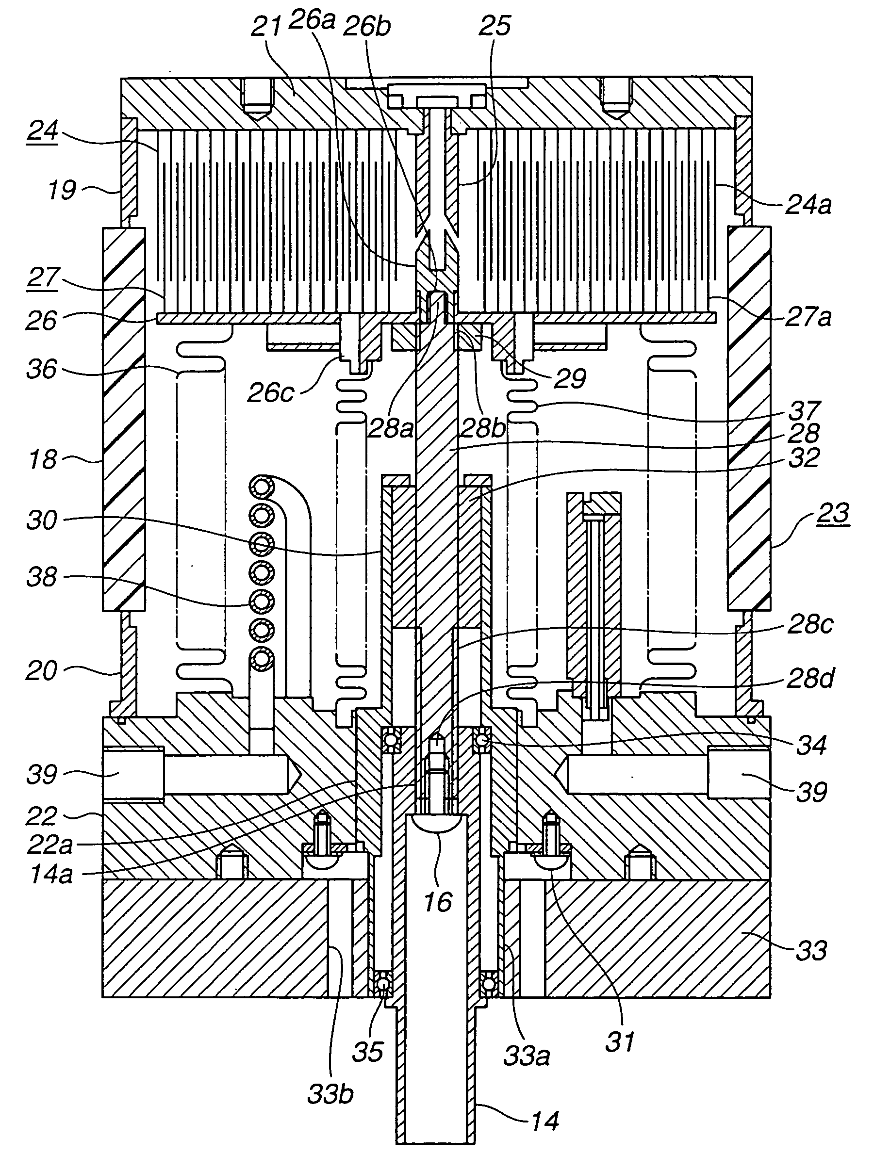
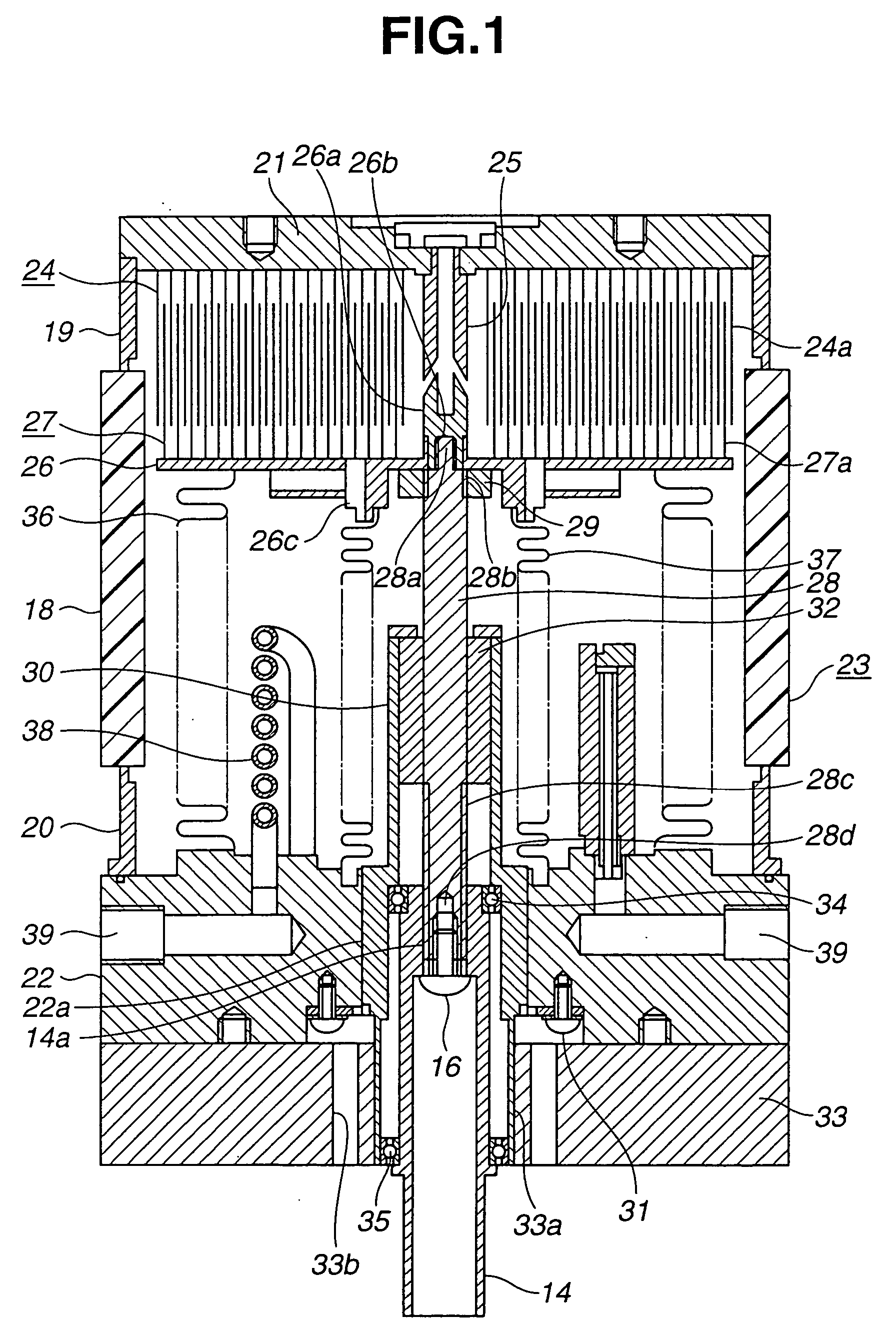
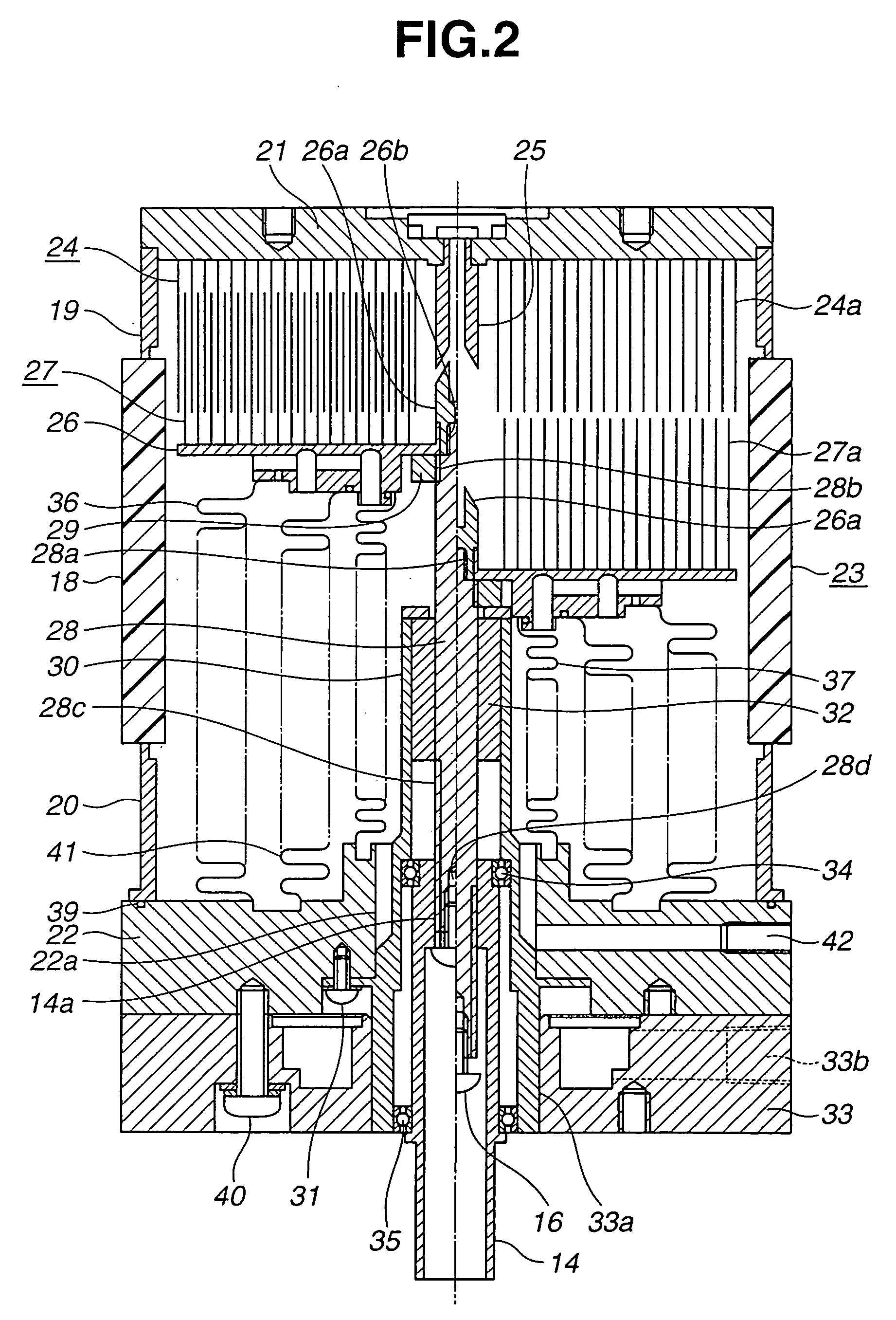
[0012] Referring to the drawings, a description will be made about preferred embodiments of a vacuum variable capacitor according to the present invention.
[0013] Referring to FIG. 3, before describing the preferred embodiments of the present invention, the structure of the typical vacuum variable capacitor will be described in detail. The vacuum variable capacitor comprises a ceramic insulating tube 1, a stationary side-end plate 2 secured to a first end of the insulating tube 1, and a movable side-end plate 4 secured to a second end of the insulating tube 1 through a connecting tube 3, thus forming a vacuum vessel 5.
[0014] A stationary electrode 6 is comprised of a plurality of cylindrical electrode plates 6a with different diameters mounted concentrically to the inner surface of the stationary side-end plate 2. A center pin 7 is arranged in the center of the inner surface of the stationary side-end plate 2 through a stationary guide 8. A movable-plate support plate 9 is disposed...
PUM
 Abstract
Description
Claims
Application Information