
Display, Device, Method, and Computer Program for Indicating a Clear Shot

a technology of clear shot and computer program, which is applied in the field of clear shot display, device, method, computer program, etc., can solve the problems of repeating the process, missing the shot altogether, and interfering with the trajectory of the projectil

Active Publication Date: 2012-02-23
EVRIO
View PDF7 Cites 53 Cited by
  • Summary
  • Abstract
  • Description
  • Claims
  • Application Information

AI Technical Summary

Benefits of technology

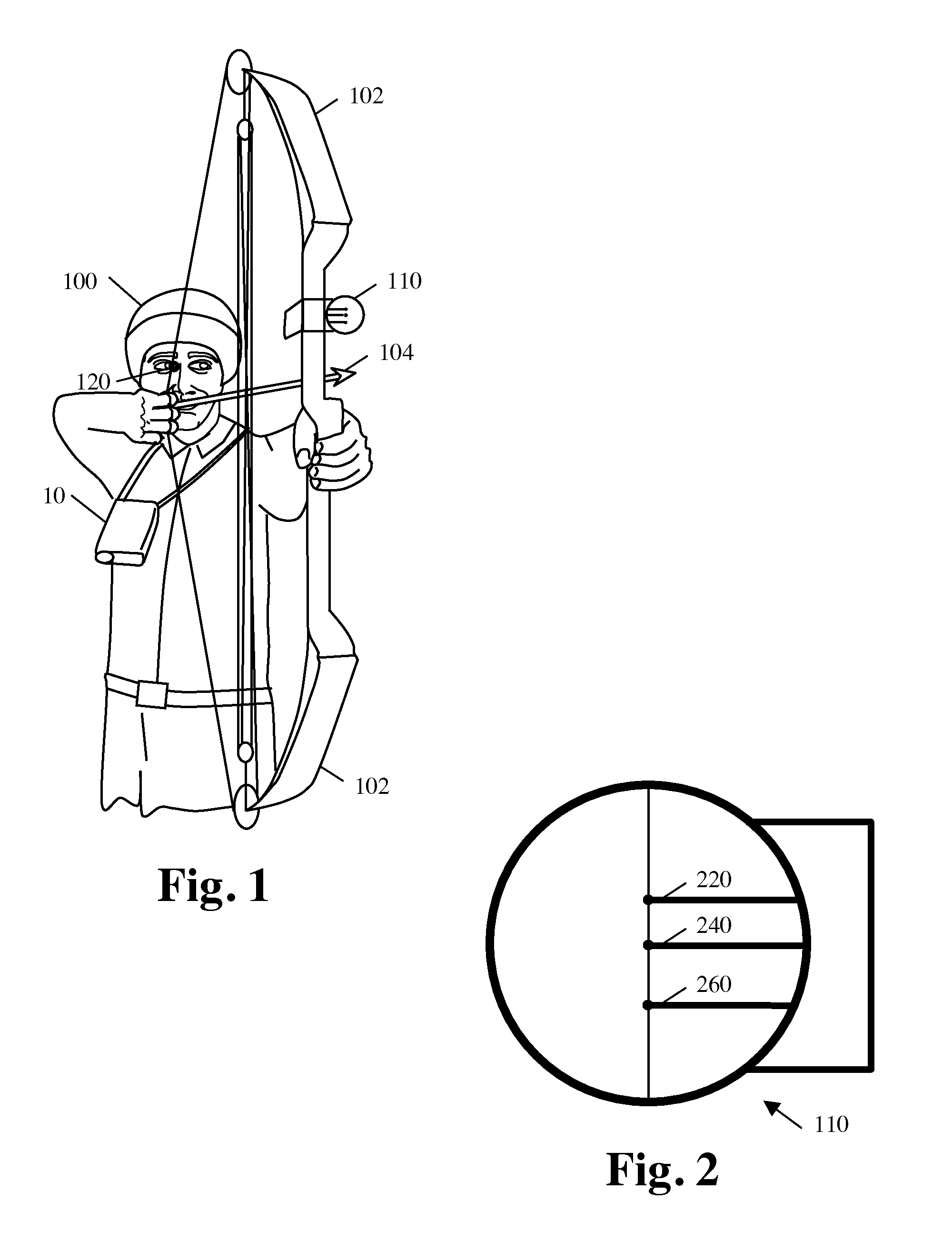
The present invention is an improved rangefinder that helps archers visualize the trajectory of their projectile, giving them more confidence in their shot. The rangefinder device has multiple pins and a display that shows the information about the distance of the target. This technology makes it easier for archers to hit their target with accuracy.

Problems solved by technology

This patent describes an improvement to handheld rangefinders called advanced rangefinders. These rangefinders provide better information than traditional rangefinders because they can detect the direction and speed of a moving target. However, current rangefinders still require multiple steps and movements before making a shot, allowing the target to move away if unnoticed. Additionally, conventional rangefinders don't correlate well with the user's bow sight pins. Therefore, the technical problem addressed by this patent is improving the accuracy and efficiency of hunters and bow players who rely on rangefinders and bow sights.

Method used


Image

  • Display, Device, Method, and Computer Program for Indicating a Clear Shot
  • Display, Device, Method, and Computer Program for Indicating a Clear Shot
  • Display, Device, Method, and Computer Program for Indicating a Clear Shot

Examples


Embodiment Construction

[0093]The following detailed description of the invention references the accompanying drawings that illustrate specific embodiments in which the invention can be practiced. The embodiments are intended to describe aspects of the invention in sufficient detail to enable those skilled in the art to practice the invention. Other embodiments can be utilized and changes can be made without departing from the scope of the present invention. The following detailed description is, therefore, not to be taken in a limiting sense. The scope of the present invention is defined only by the appended claims, along with the full scope of equivalents to which such claims are entitled.

Projectile Trajectories

[0094]FIG. 7A is a diagram illustrating a first range to a target T and an associated projectile trajectory 2. The rangefinder device 10 is show level such and the associated projectile trajectory leaves the weapon and enters the target at substantially the same true elevation (horizontal line 4)....


PUM


Abstract

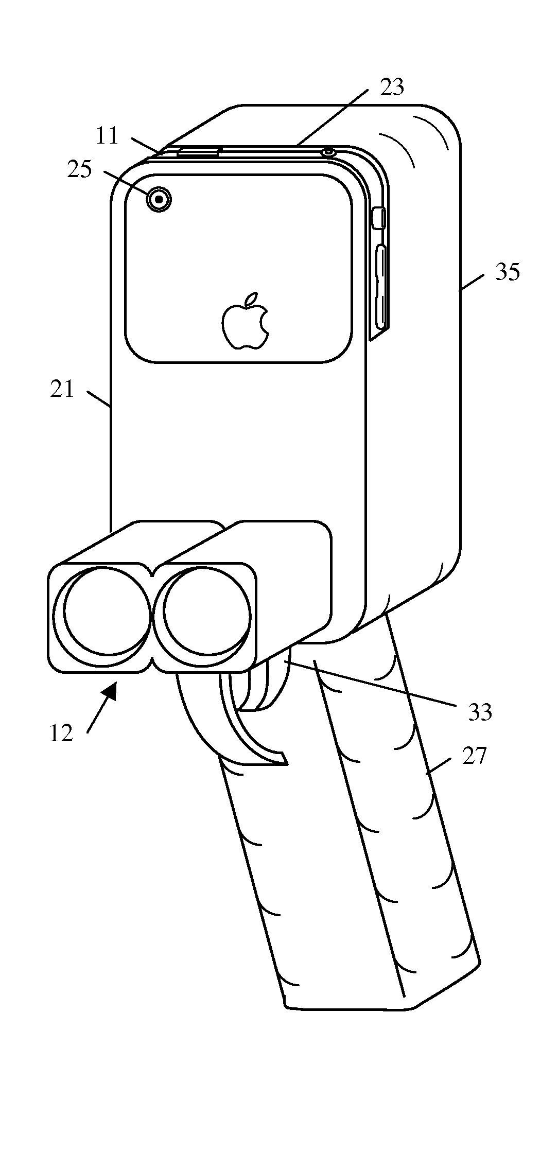
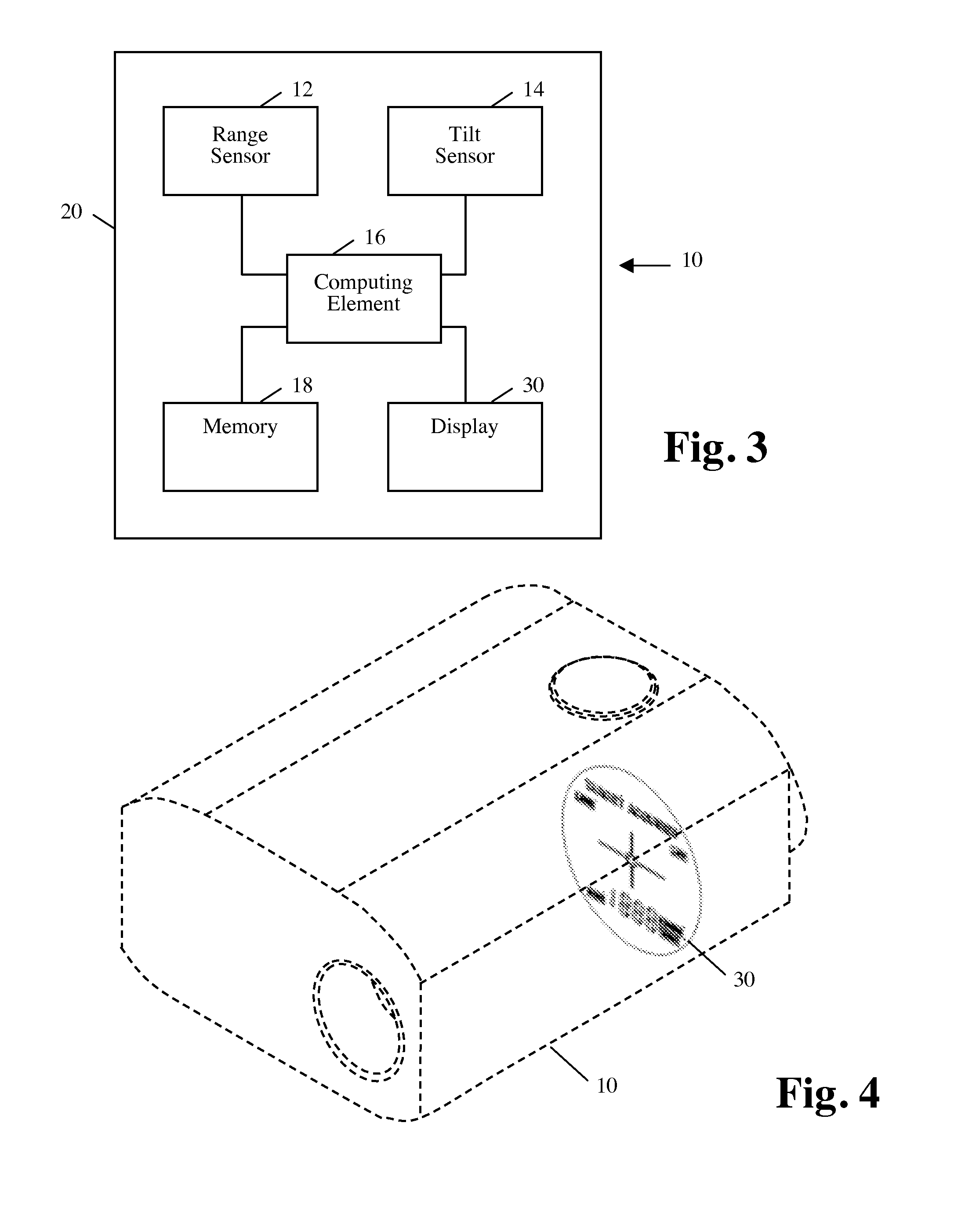
An improved display provides information regarding a projectile trajectory so that a user is informed whether or not there is a clear shot. Such information facilitates accurate, effective, and safe firearm and bow use by providing indications regarding obstacles that are between the shooter and target and which may or may not be in the projectile trajectory. The improved display provides one or more path indicators shown over the cross hairs. In some embodiments the highest point in the projectile trajectory (being a true aim point) is indicated in relation to the visualized target and possible obstacles. An improved rangefinder device generally includes a range sensor operable to determine a first range to a target, a tilt sensor operable to determine an angle to the target relative to the device, and a computing element, coupled with the range sensor and the tilt sensor, operable to determine an accurate projectile trajectory based on the first range and the determined angle. In some embodiments any obstacle in the projectile trajectory is automatically ranged and an indication is provided that the obstacle will interfere with the clear shot. A game display embodiment provides education regarding the technology. Enhanced rangefinders have digital cameras and high-resolution displays. Some embodiments adapt a mobile smart device such as an iPhone with a range sensor to be a high resolution rangefinder with a touch screen, GPS, and video analysis capabilities.

Description


Claims


Application Information

Patent Timeline
Owner EVRIO
Learn More