AI technical title is built by Patsnap AI team. It summarizes the technical point description of the patent document.
a three-dimensional imaging and monocular technology, applied in the field of imaging, can solve the problems of object displacement, high cost of multiple camera/lens system, and high computational cost of processing large target feature disparities between one sensor and another,
Active Publication Date: 2012-03-08
MEDIT CORP
View PDF10 Cites 26 Cited by
Summary
Abstract
Description
Claims
Application Information
AI Technical Summary
This helps you quickly interpret patents by identifying the three key elements:
Problems solved by technology
Method used
Benefits of technology
Problems solved by technology
However, in machine vision systems this approach has shortcomings, such as the high cost of multiple camera / lens systems and the high computational cost of processing large target feature disparities between one sensor and another.
However, unlike stereo systems, the object is displaced in both the horizontal and vertical directions among the three cameras.
Method used
Image
Click on the blue label to locate the original text in one second.
Reading with bidirectional positioning of images and text.
Examples
Embodiment Construction
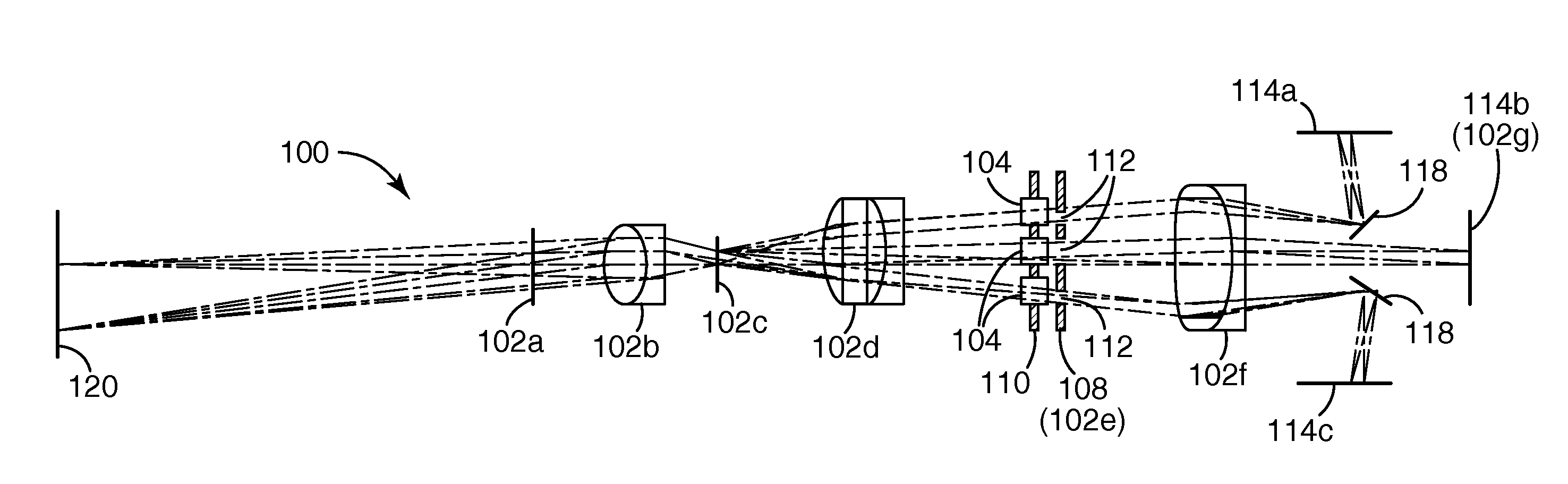
[0069]It will be understood that the ray traces and lenses depicted in the following figures are for purposes of illustration only, and depict optical paths generally in the disclosed systems. The ray traces and lens shapes should not be understood to limit the scope of the invention in any sense including the magnitude, direction, or focus of light rays or bundles passing through various optical components, notwithstanding any variations in number, direction, shape, position or size thereof, except as expressly indicated in the following detailed description.
[0070]Referring to FIG. 1, a schematic diagram of an imaging system 100 in accordance with one preferred embodiment of the present disclosure is depicted, including various optional components. The imaging system 100 may include a primary optical facility 102, which may be employed in any kind of image processing system. In general, a primary optical facility refers herein to an optical system having one optical channel. Typica...
PUM
Abstract
A three-dimensional imaging system uses a single primary optical lens along with various configurations of apertures, refocusing facilities, and the like to obtain three offset optical channels each of which can be separately captured with an optical sensor.
Description
[0001]This application is a continuation of application Ser. No. 12 / 279,097, filed Aug. 12, 2008; which was a national stage filing under 35 U.S.C. 371 of PCT / US2007 / 003947, filed Feb. 13, 2007, which International Application was published by the International Bureau in English on Aug. 23, 2007, which claims benefit of U.S. Provisional Application No. 61 / 733,132, filed Feb. 13, 2006, U.S. application Ser. No. 11 / 530,413, filed Sep. 8, 2006, which is now Issued U.S. Pat. No. 7,819,591, and U.S. application Ser. No. 11 / 530,428, filed Sep. 8, 2006, which is now Issued U.S. Pat. No. 7,372,642, the disclosure of which is incorporated by reference in their entirety herein.BACKGROUND[0002]1. Field of the Invention[0003]This invention relates to the field of imaging, and more particularly to the field of pupil sampling for multi-view three-dimensional imaging.[0004]2. Description of the Related Art[0005]One approach to capturing three-dimensional depth information is the use of a pair of t...
Claims
Application Information
Patent Timeline
Application Date:The date an application was filed.
Publication Date:The date a patent or application was officially published.
First Publication Date:The earliest publication date of a patent with the same application number.
Issue Date:Publication date of the patent grant document.
PCT Entry Date:The Entry date of PCT National Phase.
Estimated Expiry Date:The statutory expiry date of a patent right according to the Patent Law, and it is the longest term of protection that the patent right can achieve without the termination of the patent right due to other reasons(Term extension factor has been taken into account ).
Invalid Date:Actual expiry date is based on effective date or publication date of legal transaction data of invalid patent.
Patent Type & AuthorityApplications(United States)

