Display device

a display device and display technology, applied in the field of display devices, can solve the problems of narrow frame region and inability to eliminate in principle, and achieve the effect of suppressing the feeling of unnaturalness

Inactive Publication Date: 2012-03-22
SHARP KK
View PDF10 Cites 46 Cited by
  • Summary
  • Abstract
  • Description
  • Claims
  • Application Information

AI Technical Summary

Benefits of technology

[0015]The present invention provides a display device for visually obscuring the frame re

Problems solved by technology

In existing liquid crystal display devices, the frame regio

Method used


Image

  • Display device
  • Display device
  • Display device

Examples


Embodiment Construction

[0041]Hereinafter, embodiments of the present invention will be described with reference to the drawings.

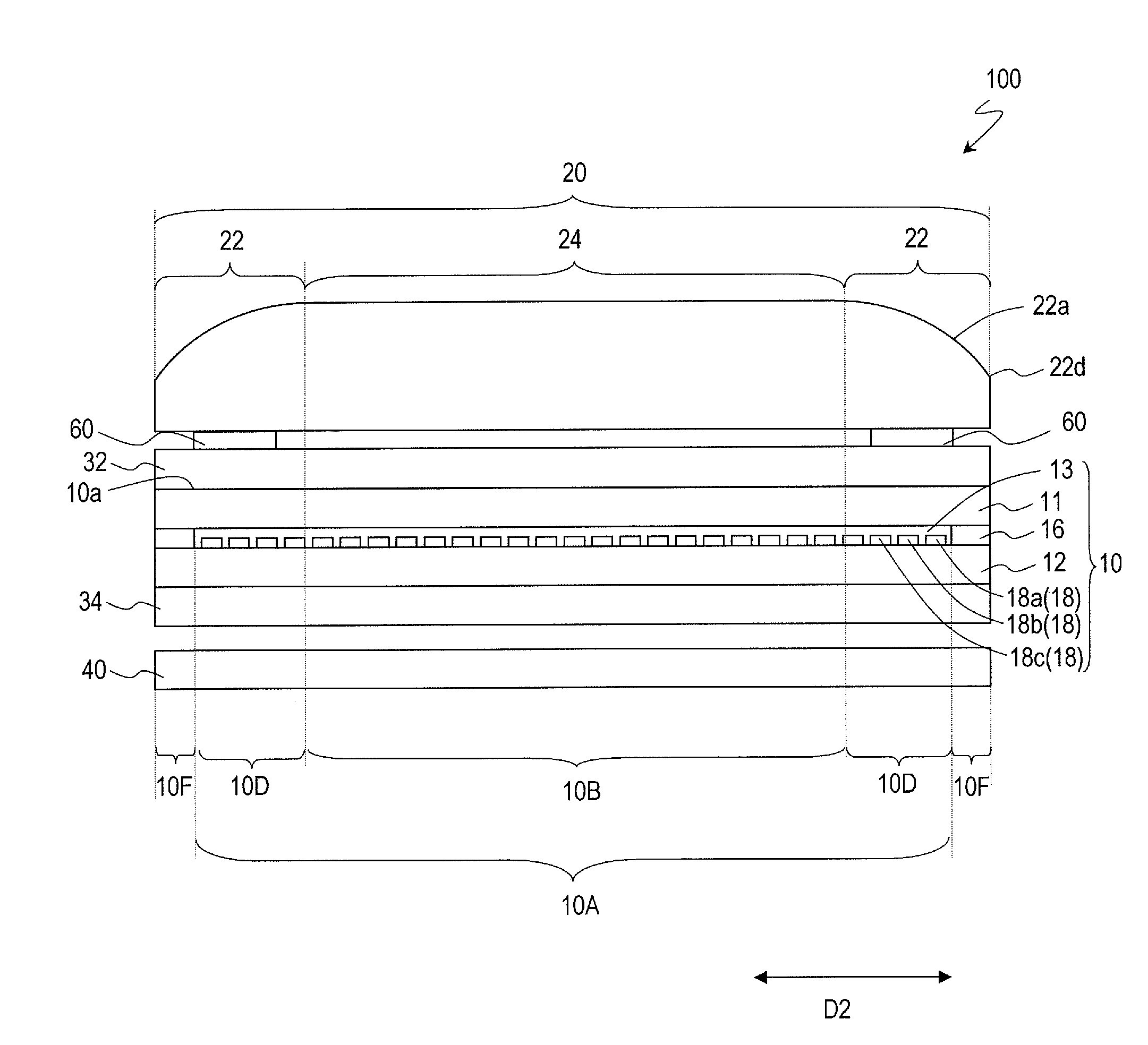
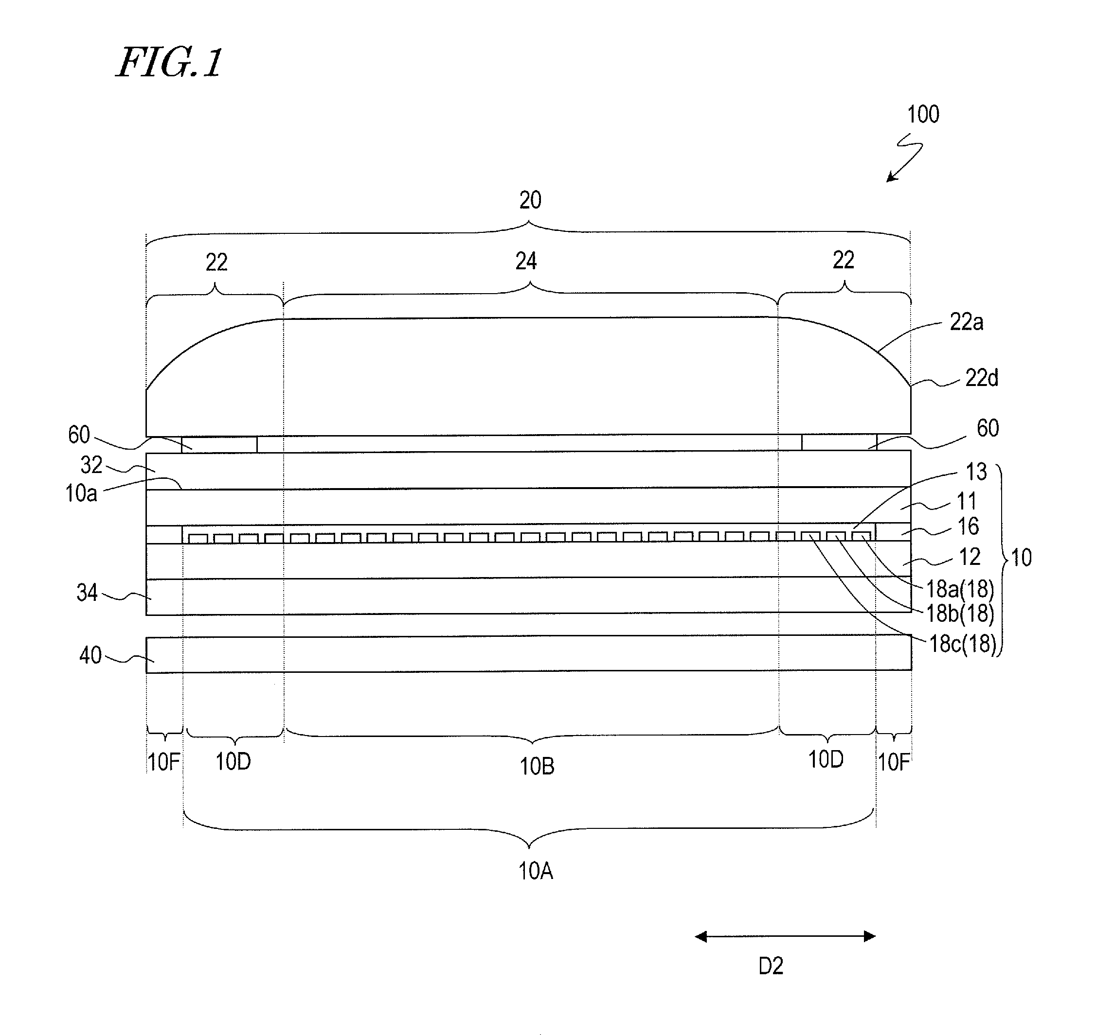
[0042]FIG. 1 is a schematic cross-sectional view of a liquid crystal display device 100. As shown in FIG. 1, the liquid crystal display device 100 includes one liquid crystal display panel 10, a light-transmitting cover 20 provided on the viewer's side of the liquid crystal display panel 10, light diffusion structures 60, an upper polarizer plate 32, a lower polarizer plate 34, and a backlight device 40.

[0043]The liquid crystal display panel 10 includes a display region 10A and frame regions 10F provided outside the display region 10A. In the display region 10A, a plurality of pixels are located in a matrix, namely, in a row direction and a column direction perpendicular to the row direction. FIG. 1 is a cross-sectional view of the liquid crystal display device 100 taken along a plane perpendicular to the column direction (direction perpendicular to the sheet of FIG. 1; hereinaft...


PUM


Abstract

A direct-viewing type display device (100) according to the present invention includes a display panel (10) including a display region (10A) which has a plurality of pixel lines (18) extending in a first direction and a frame region (10F), the display region and the frame region having a border extending in the first direction therebetween; and a light-transmitting cover (20). The plurality of pixel lines include a first pixel line (18a) adjoining the border, a second pixel line (18b), and a third pixel line (18c). The first pixel line, the second pixel line and the third pixel line are of different colors from each other. The light-transmitting cover includes a lens portion (22) located so as to stride over the border, the lens portion refracting a part of light, going out from the display region, toward the frame region. A light diffusion structure (60) is provided between the lens portion and a part of the display panel including the first pixel line, the second pixel line and the third pixel line. The present invention provides a display device for visually obscuring the frame region of the display panel and suppressing the sense of unnaturalness given to the viewer.

Description

TECHNICAL FIELD[0001]The present invention relates to a display device and particularly to a direct-viewing type display device.BACKGROUND ART[0002]A liquid crystal display device includes a liquid crystal display panel, a backlight device, circuits for supplying various electrical signals to the liquid crystal display panel, and a power supply, as well as a housing for accommodating these components. The liquid crystal display panel has a display region in which a plurality of pixels are arrayed and a frame region surrounding the display region. In the display region, pixel electrodes and TFTs are provided. In the frame region, a sealing portion, a portion in which driving circuits are mounted, and the like are provided. The frame region, in which no pixels are arrayed, does not contribute to displaying. In existing liquid crystal display devices, the frame region has been narrowed, but cannot be eliminated in principle.[0003]When a large screen is constructed by arraying a plurali...

Claims


Application Information

Patent Timeline
IPC IPC(8): G02F1/1335
CPCG02B5/0215G02B5/0231G02B27/0955G02F2001/133562G02F1/133504G02F2001/133388G02F1/133526G02B27/30G02F1/133388G02F1/133562
Inventor WATANABE, HISASHI
Owner SHARP KK
Why Eureka
Try Eureka