Image forming apparatus

a technology of image forming apparatus and forming apparatus, which is applied in the direction of electrographic process apparatus, instruments, optics, etc., can solve the problems of degrading and achieve the effect of suppressing a generation of energization deterioration and improving the image quality of the image forming apparatus

Active Publication Date: 2012-03-29
BROTHER KOGYO KK
View PDF4 Cites 6 Cited by
  • Summary
  • Abstract
  • Description
  • Claims
  • Application Information

AI Technical Summary

Benefits of technology

[0007]In view of the above, it is desirable to improve the image quality of the i

Problems solved by technology

Energization deterioration may degrade the i

Method used


Image

  • Image forming apparatus
  • Image forming apparatus
  • Image forming apparatus

Examples


Embodiment Construction

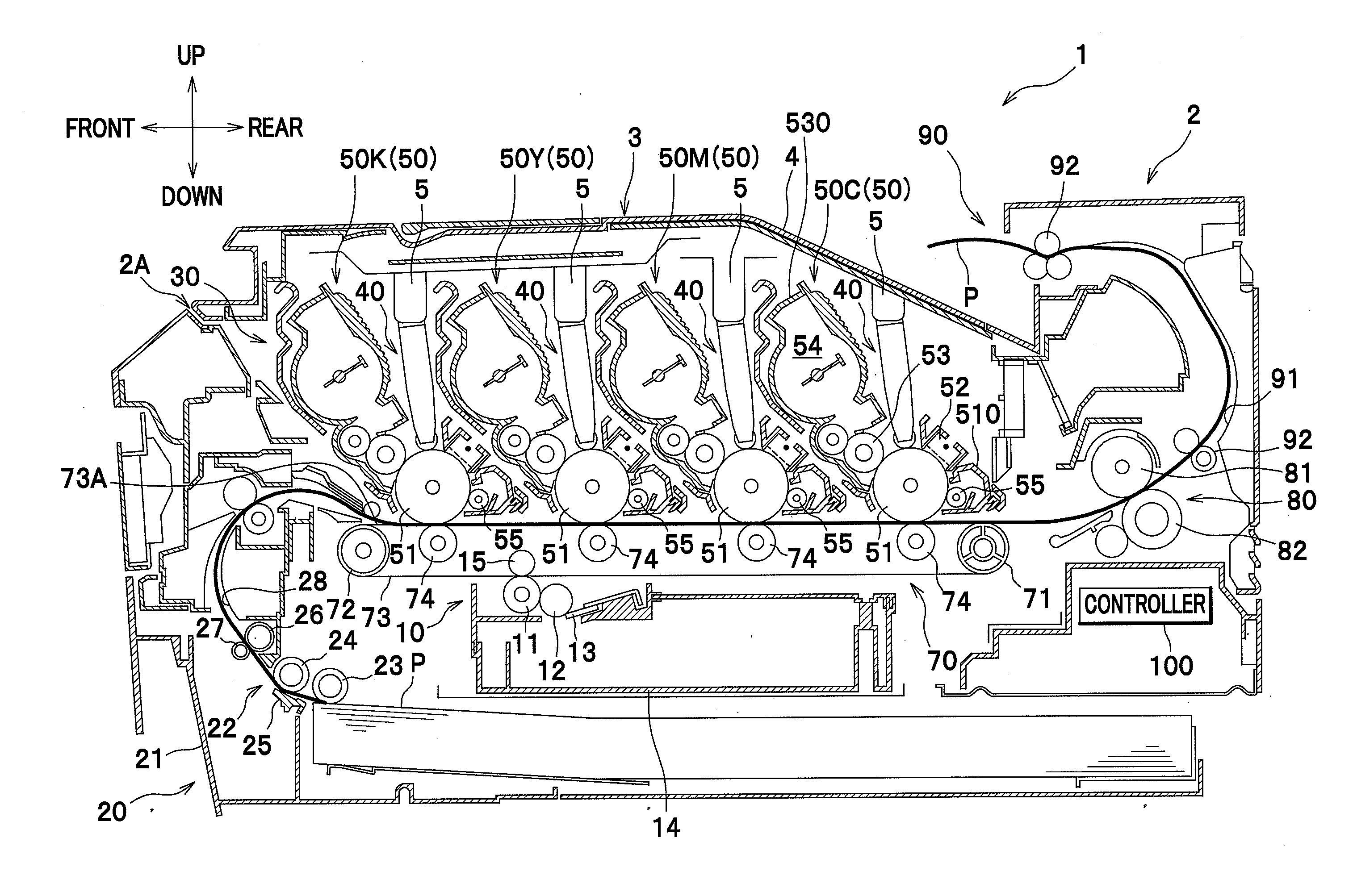
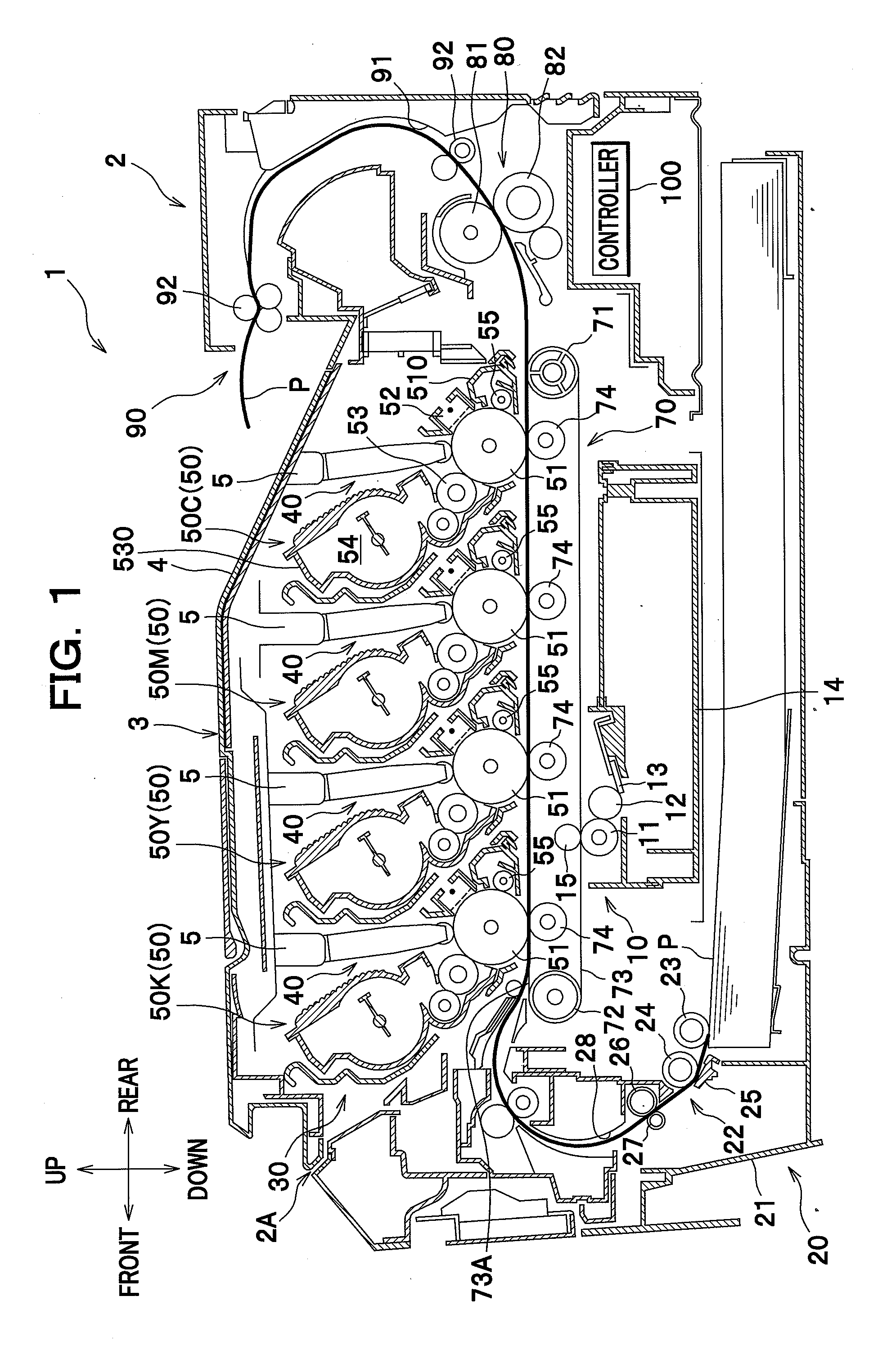
[0019]Detailed description will be given of illustrative embodiments of the present invention with reference to the drawings. In the following description, unless otherwise stated, directions of a color laser printer refer to the directions as seen from a user facing to the printer during its use. To be more specific, with reference to FIG. 1, the left-hand side of the drawing sheet corresponds to the “front” side of the printer, the right-hand side of the drawing sheet corresponds to the “rear” side of the printer, the front side of the drawing sheet corresponds to the “right” side of the printer, and the back side of the drawing sheet corresponds to the “left” side of the printer. Similarly, the direction extending from top to bottom of the drawing sheet corresponds to the “vertical” or “up / down (upper / lower or top / bottom)” direction of the printer.

[0020]As seen in FIG. 1, a color printer 1 comprises a main body casing 2, and several components housed within the main body casing 2...


PUM


Abstract

An image forming apparatus includes a controller capable of performing a printing control and a cleaning control. In the printing control, developer images carried on the image carriers are transferred toward the opposing surface or a recording sheet by applying a transfer current between each of the image carriers and the transfer device. In the cleaning control, developer collected by the cleaning rollers is transferred toward the image carriers and the transfer device and collected by the cleaning device by applying a transfer current between each of the image carriers and the transfer device and switching an electric field established between the image carrier and the corresponding cleaning roller. The controller is configured to control the transfer current such that an average absolute value of the transfer current in the cleaning control is smaller than that in the printing control.

Description

BACKGROUND OF THE INVENTION[0001]1. Field of the Invention[0002]The present invention relates to an image forming apparatus capable of performing a cleaning control in which toner (developer) collected by cleaning rollers is transferred to a belt (transfer device) through photoconductor drums (image carriers) and collected by a cleaning device.[0003]2. Description of Related Art[0004]Conventionally, there is known an image forming apparatus comprising a plurality of photoconductor drums, a plurality of cleaning rollers each of which is adjacent to a corresponding photoconductor drum and configured to collect toner adhering to the surface of the corresponding photoconductor drum, a rotatable endless belt arranged opposite the photoconductor drums, a plurality of transfer rollers each of which is arranged opposite the corresponding photoconductor drum with the belt interposed therebetween, and a cleaning device for collecting toner adhering to the belt. In this image forming apparatus...

Claims


Application Information

Patent Timeline
IPC IPC(8): G03G15/16
CPCG03G15/168G03G2215/1661G03G21/00
Inventor AMAIKE, TAKUYAFURUKAWA, TOSHIO
Owner BROTHER KOGYO KK
Why Eureka
Try Eureka