Electric ground clamp with pivoted jaws and single attached adjusting bolt and terminal block

a ground clamp and jaw technology, applied in the direction of coupling device connection, connection contact member material, coupling device details, etc., can solve the problems of loose parts which may be lost, difficult to disassemble and reassemble the ground clamp around the electrical conduit in difficult to reach locations, and difficult to reach locations

a ground clamp and jaw technology, applied in the direction of coupling device connection, connection contact member material, coupling device details, etc., can solve the problems of loose parts which may be lost, difficult to disassemble and reassemble the ground clamp around the electrical conduit in difficult to reach locations, and difficult to reach locations

US20120088380A1Active Publication Date: 2012-04-12BRIDGEPORT FITTINGS LLC

Image

  • Electric ground clamp with pivoted jaws and single attached adjusting bolt and terminal block
  • Electric ground clamp with pivoted jaws and single attached adjusting bolt and terminal block
  • Electric ground clamp with pivoted jaws and single attached adjusting bolt and terminal block

Examples


Embodiment Construction

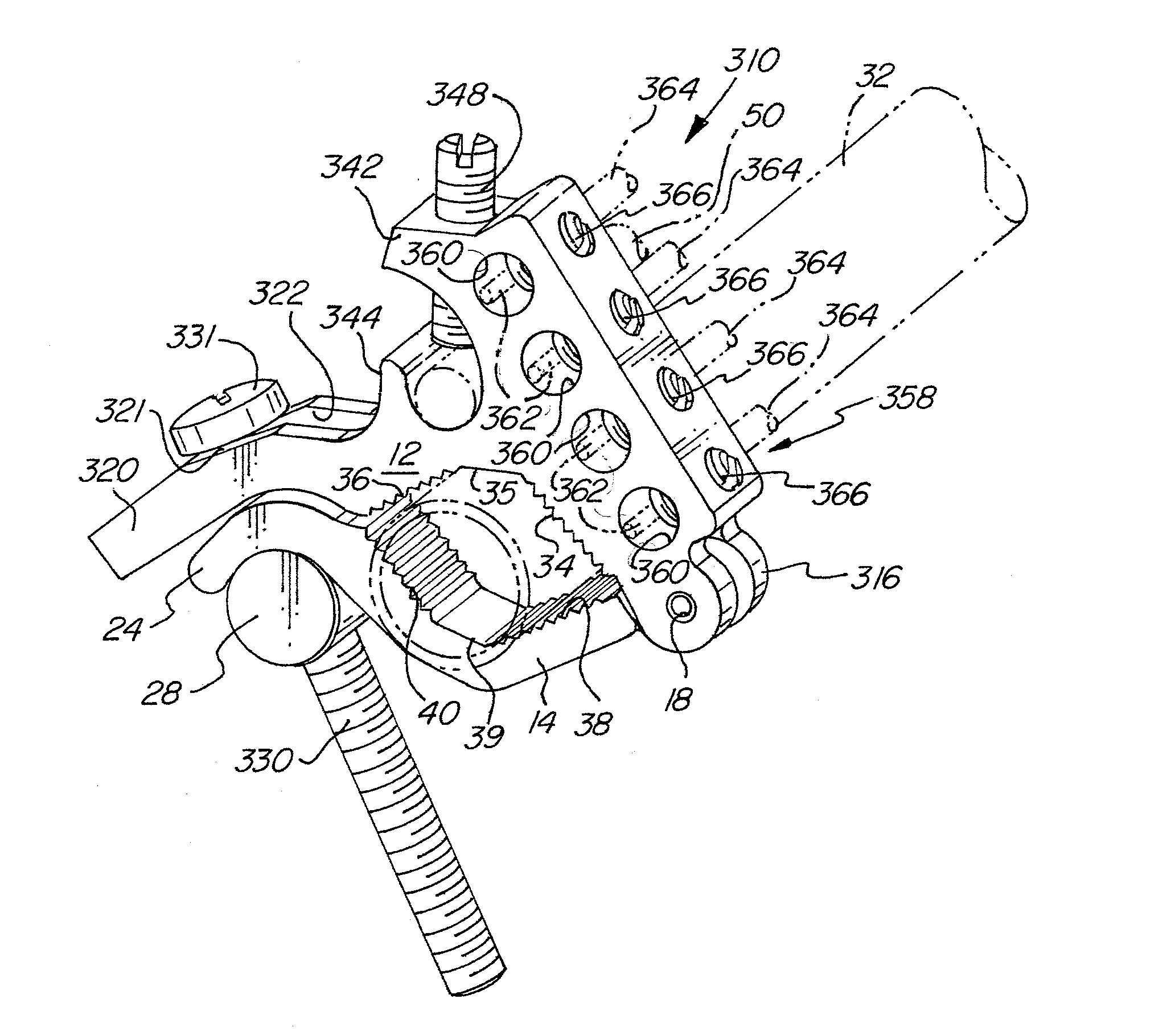
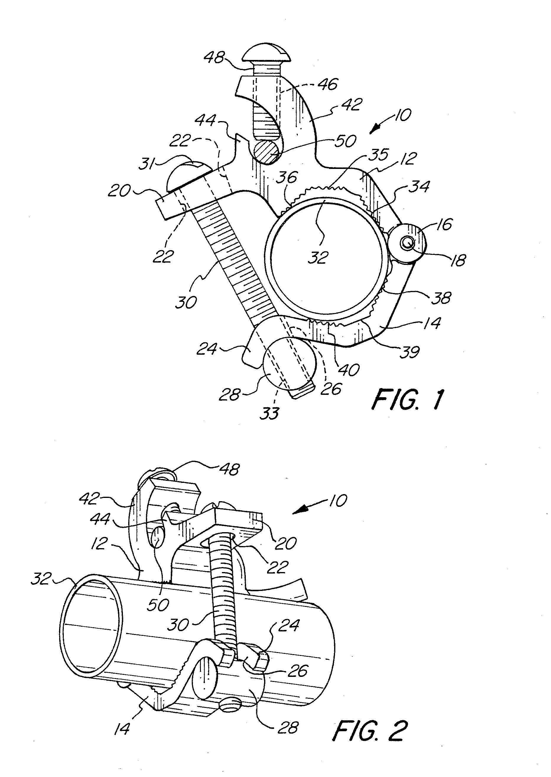
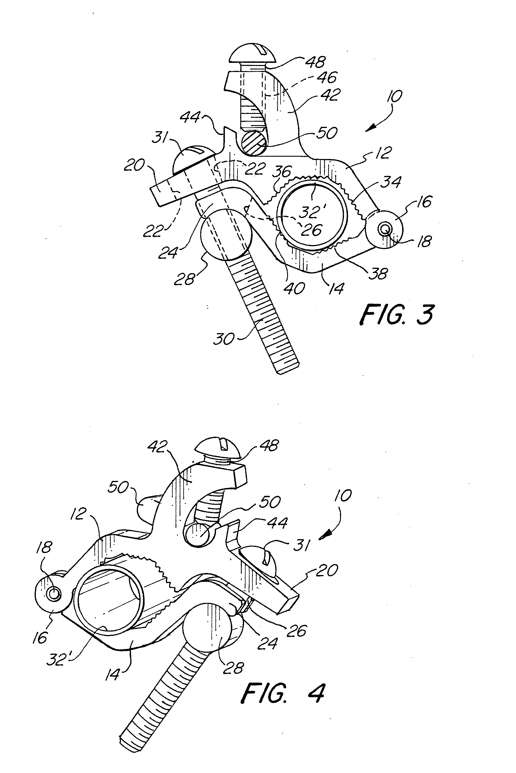
[0039]FIGS. 1-7B illustrate a first embodiment of the invention. In FIG. 1 the ground clamp 10 comprises a first jaw 12 coupled to a second jaw 14 by a hinge 16 and a hinge pin 18. The first jaw 12 has a first distal end 20 having an elongated hole 22 therein. The second jaw 14 has a second distal end forming a curve having a slot 26 formed therein forming a curved fork 24. A cylindrical nut 26 has a diameter substantially matching the curve or radius of the curved fork 24 formed on to the second distal end of the second jaw 14. The cylindrical nut 28 is held on the threaded portion or end 33 of bolt 30 having a head 31. The head 31 of the bolt 30 retains the bolt 30 within the elongated hole 22. The conduit 32, which may be electrical metallic tubing or EMT or a rigid conduit, is held between the first and second jaws 12 and 14. The first jaw 12 has a first inside angled jaw surface 34 and a first outside angled jaw surface 36 separated by a first intermediate surface 35. The secon...


PUM


Abstract

An adjustable ground clamp for easy positioning onto electric conduits of different diameters and grounding multiple electrical devices. A first and a second jaw are pivotally connected and have differently angled jaw surfaces. A distal end of the first jaw has an elongated hole and a distal end of the second jaw has a curved fork having a slot for receiving a bolt with a cylindrical nut. A fastener connects a ground conductor or wire to the ground clamp. A terminal block accepts ground conductors from multiple different electrical devices. The jaws may be easily separated for placement of an electrical conduit without separating or detaching any parts from the ground clamp, making attachment to an electrical conduit quick, easy, and secure. The terminal block permits different electrical devices to be grounded with a single ground clamp.

Description

RELATED APPLICATION[0001]This application is a continuation-in-part of application Ser. No. 12 / 899,705 filed Oct. 7, 2010.FIELD OF THE INVENTION[0002]The present invention relates in general to an electric ground clamp for attaching to an electrical conduit, and more particularly to an adjustable clamp that is easily and quickly installed and that provides multiple grounding connections.BACKGROUND OF THE INVENTION[0003]In many electrical applications, it is often necessary to electrically ground a conduit. Often a ground clamp is attached to the conduit. A ground conductor or wire is then attached or connected to the ground clamp providing continuity or an electrical path to ground. Typically a compression clamp is used that often has two opposing screws or fasteners that are alternately tightened to draw two opposing sections of the clamp together substantially equally, so as to clamp down on the electrical conduit.[0004]One such ground clamp is disclosed in U.S. Pat. No. Des. 243,...

Claims


Application Information

Patent Timeline
12 Apr 2012
Publication
US20120088380A1
IPC
H01R4/66
CPC
H01R4/36; H01R4/643; H01R4/42; H01R4/40
Inventors
SMITH, LAWRENCE J.